OMNI 4000/7000 Installation Guide – Rev H
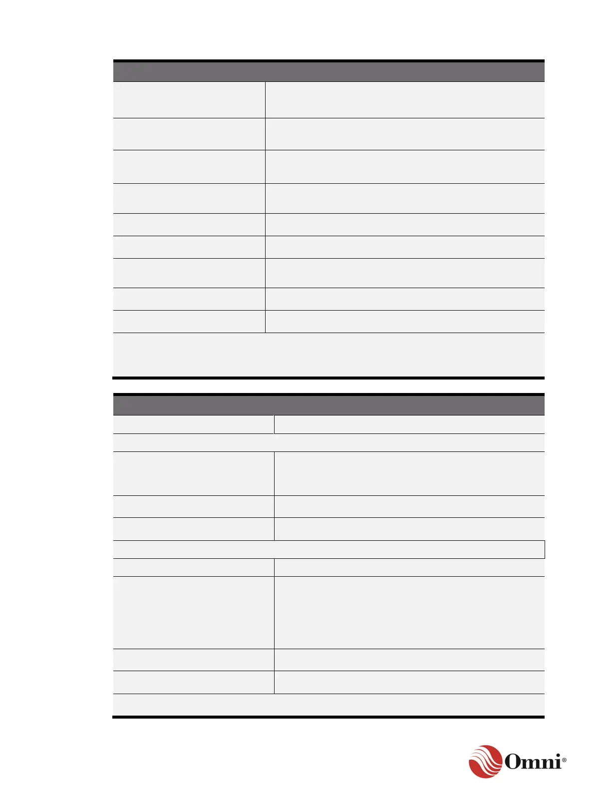
Frequency Shift Keying (FSK)
• 1 per Network – 24 Max (HT Module)
• 4 per Network – 96 Max (HM Module)
+24 VDC (+/- 0.25V) supplied from the 4/7000 Back Panel or
external DC supply
Internal Load Resistance**
Selectable for each network (250 ohms, 500 ohms or Out)
Indicators for each network (activity and status)
Minimum Input Threshold for
Carrier Detect
±250 VDC to chassis ground
* 6 HT/HM modules maximum
** If load resistance is set to “Out” position, an external load resistor from 250 – 600 ohms must
be provided.
Control Outputs/Status Inputs*
FET transistor source (referenced to DC return)
200 mA maximum per point, 500 mA maximum for the DM
module
Outputs may be pulsed at 50 Hz maximum.
• Input voltages > +5 VDC to < DC+ will be recognized
as ON (referenced to DC return).
• Input voltages < +4 VDC will be recognized as OFF
(referenced to DC return).
• 30 VDC Maximum
Operating and fault condition indicators on each channel
*10 Per DM module, one module per unit
 Loading...