3 Nomenclature and Functions
3-24
CJ2 CPU Unit Hardware User’s Manual
z Application Precautions
• Interrupt Input Units must be mounted in the locations described below.
When using a CJ2H-CPU@@-EIP CPU Unit, all Interrupt Input Units must be connected in any of
the four positions immediately to the right of the CPU Unit. If connected in any other position in
the CPU Rack or anywhere in an Expansion Rack, and I/O setting error (fatal) will occur.
• The Interrupt Input Units must be connected to slot numbers 0 to 3 even when the I/O tables are
edited using the CX-Programmer. If the Interrupt Input Units are not connected in the correct posi-
tions, an error will occur when the I/O tables are generated from the CX-Programmer. A401.10 will
turn ON to indicate an I/O setting error and A405.08 will turn ON to indicate that an Interrupt Input
Unit is in the wrong position.
Note Even if a Unit is physically in one of the correct positions, a Dummy Unit can be registered in the I/O tables,
causing a Unit to be defined in a position different from its physical position.
• There are limits to the number of Interrupt Input Units that can be mounted. If these limits are
exceeded, a too many I/O points error (fatal error) will occur.
• The input response time cannot be changed for the CJ1W-INT01, and the related portions of the
Basic I/O Unit input time constants in the PLC Setup, and the setting status in A200 to A259 will not
be valid.
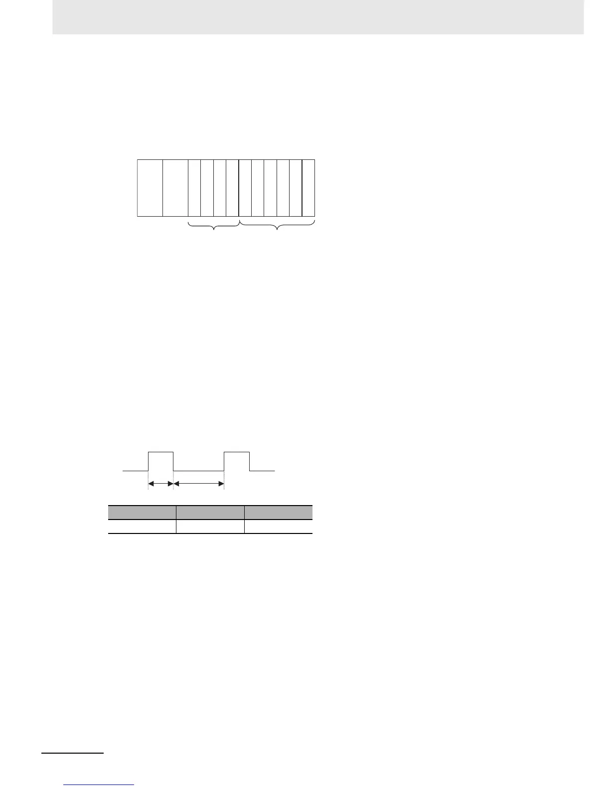
z Input Signal Width
Input signals must meet the following conditions.
Unit ON time OFF time
CJ1W-INT01 0.05 ms min. 0.5 ms min.
0 1 2 3 4 5 6 7 8 9
Power
Supply
Unit
CPU
Unit
Connect here.
Cannot be used.
ON OFF