1-9
1 Overview
CJ2 CPU Unit Hardware User’s Manual
1-3 Specifications
1
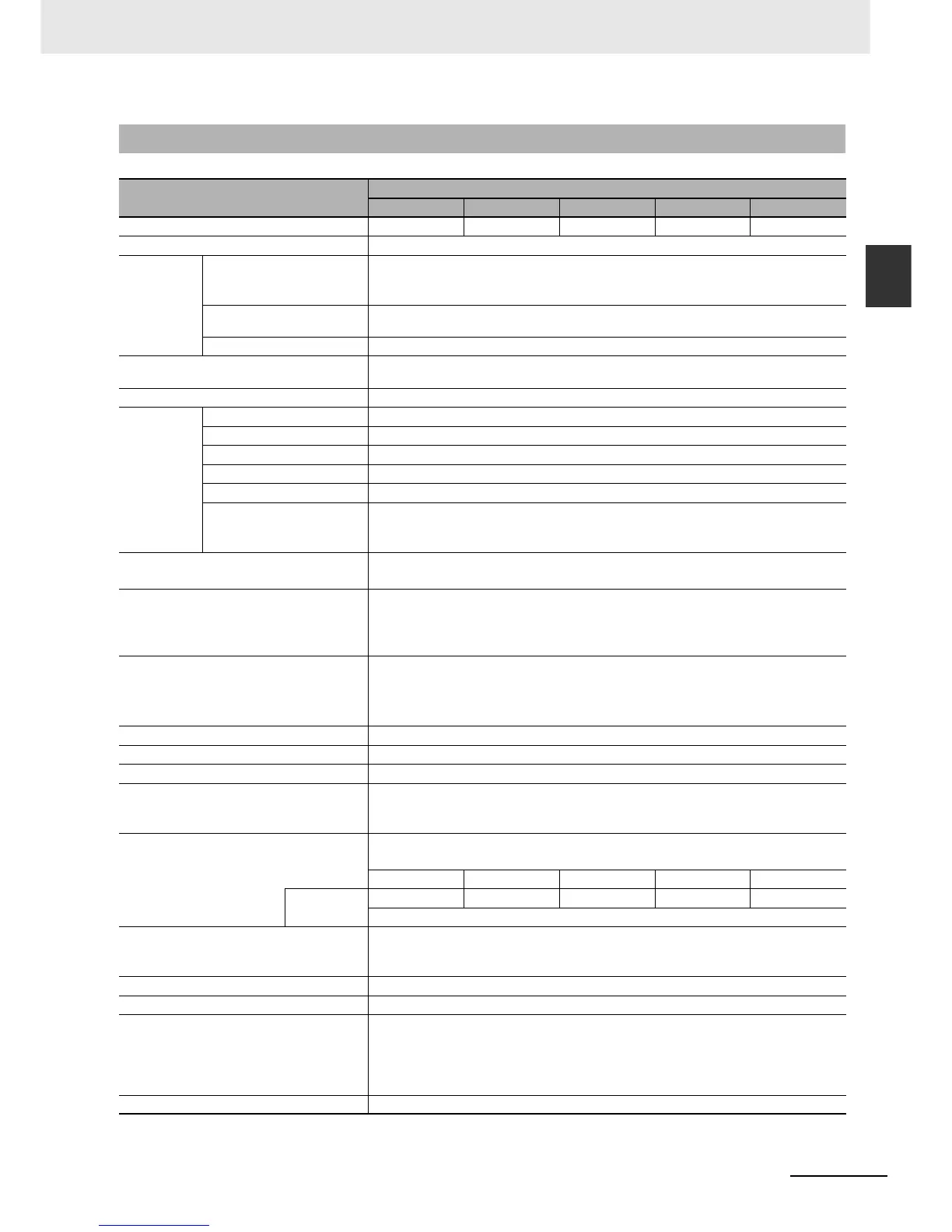
1-3-2 Performance Specifications
1-3-2 Performance Specifications
Items
CJ2H-
CPU64-EIP CPU65-EIP CPU66-EIP CPU67-EIP CPU68-EIP
User Memory 50K steps 100K steps 150K steps 250K steps 400K steps
I/O Bits 2,560 bits
Processing
Speed
Overhead Processing Time Normal Mode: 200 µs
(If tag data links are used with EtherNet/IP, add the following to the above time: 100 µs + Number of
transferred words × 0.33 µs)
Execution Time Basic Instructions: 0.016 µs min.;
Special Instructions: 0.048 µs min.
Interrupt Task Start Time 30 µs
Maximum Number of Connectable Units Total per CPU Rack or Expansion Rack: 10 Units max.;
Total per PLC: 40 Units max.
Maximum Number of Expansion Racks 3 max.
CIO Area I/O Area 2,560 bits (160 words): Words CIO 0000 to CIO 0159
Link Area 3,200 bits (200 words): Words CIO 1000 to CIO 1199
CPU Bus Unit Area 6,400 bits (400 words): Words CIO 1500 to CIO 1899
Special I/O Unit Area 15,360 bits (960 words): Words CIO 2000 to CIO 2959
DeviceNet Area 9,600 bits (600 words): Words CIO 3200 to CIO 3799
Internal I/O Area 3,200 bits (200 words): Words CIO 1300 to CIO 1499
37,504 bits (2,344 words): Words CIO 3800 to CIO 6143
Cannot be used for external I/O.
Work Area 8,192 bits (512 words): Words W000 to W511
Cannot be used for external I/O.
Holding Area 8,192 bits (512 words): Words H000 to H511
Bits in this area maintain their ON/OFF status when PLC is turned OFF or operating mode is changed.
Words H512 to H1535: These words can be used only for function blocks. They can be used only for
function block instances (i.e., they are allocated only for internal variables in function blocks).
Auxiliary Area Read-only: 31,744 bits (1,984 words)
• 7,168 bits (448 words): Words A0 to A447
• 24,576 bits (1,536 words): Words A10000 to A11535
Read/write: 16,384 bits (1,024 words) in words A448 to A1471
Temporary Area 16 bits: TR0 to TR15
Timer Area 4,096 timer numbers (T0000 to T4095 (separate from counters))
Counter Area 4,096 counter numbers (C0000 to C4095 (separate from timers))
DM Area 32k words (Bits in the DM Area can be addressed either by bit or by word.)
DM Area words for Special I/O Units: D20000 to D29599 (100 words × 96 Units)
DM Area words for CPU Bus Units: D30000 to D31599 (100 words × 16 Units)
EM Area 32k words/1 bank × 25 banks max.: E00_00000 to E18_32767 max.
(Bits in the EM Area can be addressed either by bit or by word.)
32k × 4 banks 32k × 4 banks 32k × 10 banks 32k × 15 banks 32k × 25 banks
Force-set/reset
Enabled Banks
EM3 EM3 EM6 to EM9 EM7 to EME EM11 to EM18
Force-setting/resetting is enabled only for areas specified for automatic address allocation.
Index Registers IR0 to IR15
These are special registers for storing PLC memory addresses for indirect addressing. (Index Registers
can be set so that they are unique in each task or so that they are shared by all tasks.)
Cyclic Task Flag Area 128 flags
Memory Card 128 MB, 256 MB, or 512 MB
Operating Modes PROGRAM Mode: Programs are not executed. Preparations can be executed prior to program execu-
tion in this mode.
MONITOR Mode: Programs are executed, and some operations, such as online editing, and changes
to present values in I/O memory, are enabled in this mode.
RUN Mode: Programs are executed. This is the normal operating mode.
Execution Mode Normal Mode