A-73
Appendices
CJ2 CPU Unit Hardware User’s Manual
A-1 Specifications of Basic I/O Units
App
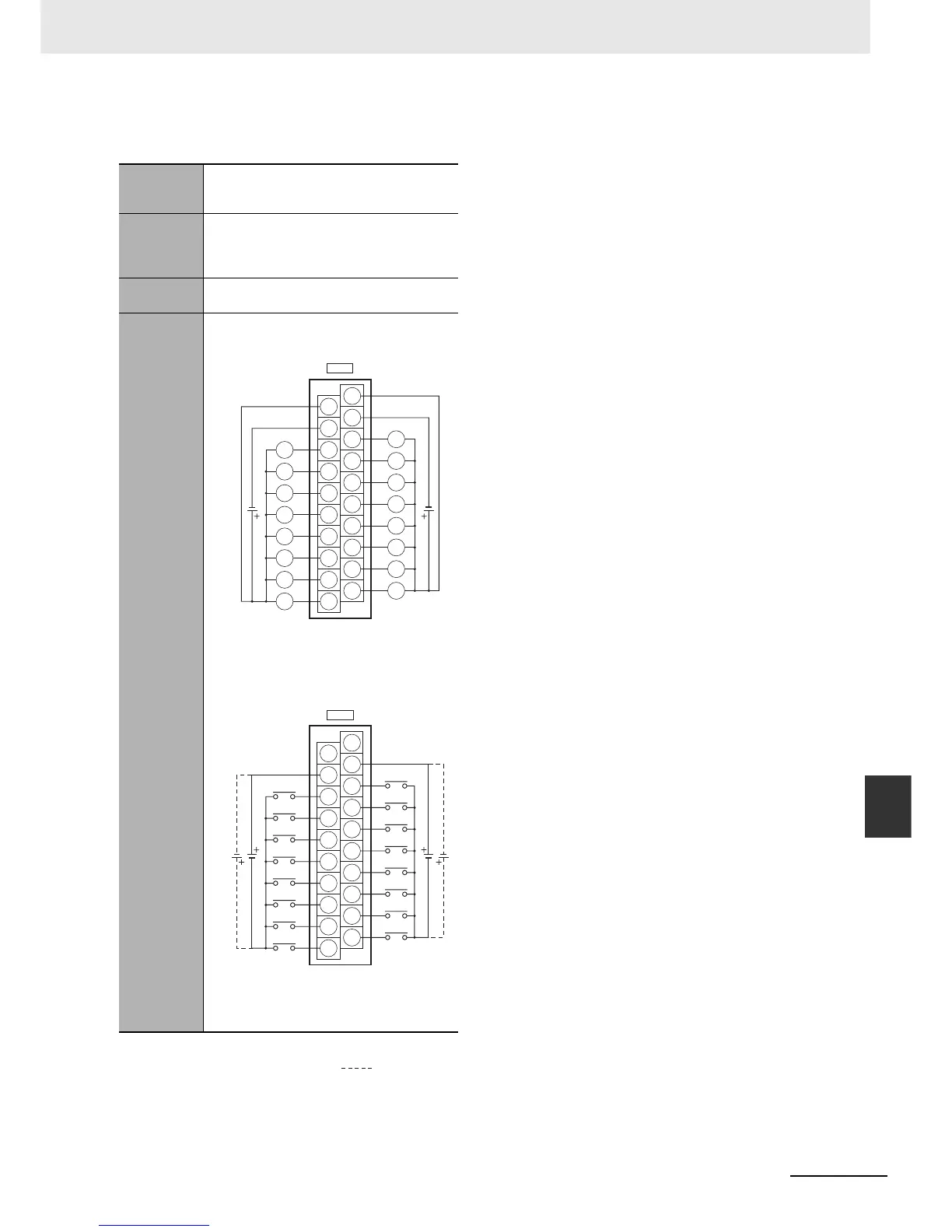
A-1-4 Connecting Connector-Terminal Block
Conversion Units and I/O Relay Terminals
z Inputs and Outputs
Note 1 The polarity for input power supply connections
indicated with dotted lines ( ) can be con-
nected in either direction.
2 The COM terminals are internally connected
inside the PLC, but they must all be wired.
Programma-
ble Control-
ler I/O Unit
CJ1W-MD231
Connector-
Terminal
Block Con-
version Unit
XW2D-20G6
Connecting
Cables
XW2Z-@@@A
Connection
diagram
A10
A1
A2
A3
A4
A5
A6
A7
A8
A9
B10
B1
B2
B3
B4
B5
B6
B7
B8
B9
CN2
A10
A1
A2
A3
A4
A5
A6
A7
A8
A9
B10
B1
B2
B3
B4
B5
B6
B7
B8
B9
CN1
L
L
L
L
L
L
L
L
L
L
L
L
L
L
L
L
07
06
05
04
03
02
01
00
07
COM
NC
06
05
04
03
02
01
00
15
COM
NC
14
13
12
11
10
09
08
15
14
13
12
11
10
09
08
12 to
24 VDC
12 to
24 VDC
24
VDC
24
VDC
Wd m
(OUT)
+V
+V
COM (0 V)
COM (0 V)
Wd (m+1)
(IN)