3-21
3 Nomenclature and Functions
CJ2 CPU Unit Hardware User’s Manual
3-3 Power Supply Units
3
3-3-3 Selecting a Power Supply Unit
Ground to a resistance of 100 Ω or less to avoid electric shock.
The internal contact turns ON when the CJ2 CPU Unit is operating (RUN or MONITOR mode). The
Power Supply Unit must be in the CPU Rack to use this output.
The alarm output is used to notify when Power Supply Unit replacement is required. The output is nor-
mally ON. The output turns OFF when the time until replacement is 6 months or less.
After determining what power supply voltage is required, whether power output terminals and a RUN
output are required, and whether replacement notification is required, calculate the current and power
requirements for each Rack.
There are two voltage groups for internal power consumption: 5 VDC and 24 VDC.
For details on the current consumption of individual Units, refer to 2-1-4 Configuration Units.
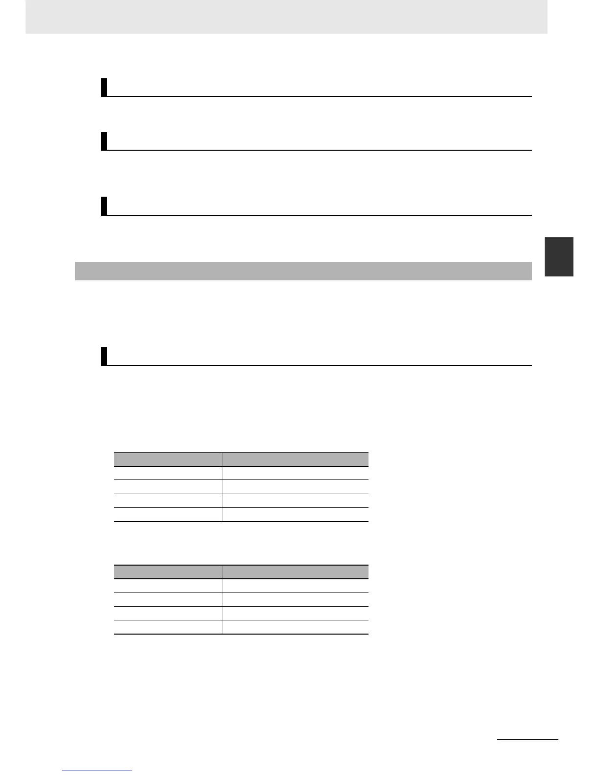
z Current Consumption at 5 VDC
The following table shows the current that can be supplied to Units (including the CJ2 CPU Unit) that
use 5-VDC power.
z Current Consumption at 24 VDC
The following table shows the current that can be supplied to Units that use 24-VDC power supply.
GR
RUN Output (CJ1W-PA205R Only)
Alarm Output (CJ1W-PA205C Only)
3-3-3 Selecting a Power Supply Unit
Condition 1: Current Requirements
Model Maximum current at 5 VDC
CJ1W-PA205R/205C 5.0 A
CJ1W-PA202 2.8 A
CJ1W-PD025 5.0 A
CJ1W-PD022 2.0 A
Model Maximum current at 24 VDC
CJ1W-PA205R/205C 0.8 A
CJ1W-PA202 0.4 A
CJ1W-PD025 0.8 A
CJ1W-PD022 0.4 A