6-7
6 Troubleshooting
CJ2 CPU Unit Hardware User’s Manual
6-1 CPU Unit Errors
6
6-1-7 Handling Errors
This section describes the measures to take for the errors that most commonly occur. First check the
error status. Then, make a preliminary determination of the cause of the error, confirm the cause, cor-
rect the error, and take measures to ensure that it will not occur again. For all other errors, refer to A-3
Fatal and Non-fatal Error Details.
A power supply error occurs when a voltage of 5 V is not output from the Power Supply Unit.
*1 The following table shows the allowable power supply ranges for each Power Supply Unit model.
6-1-7 Handling Errors
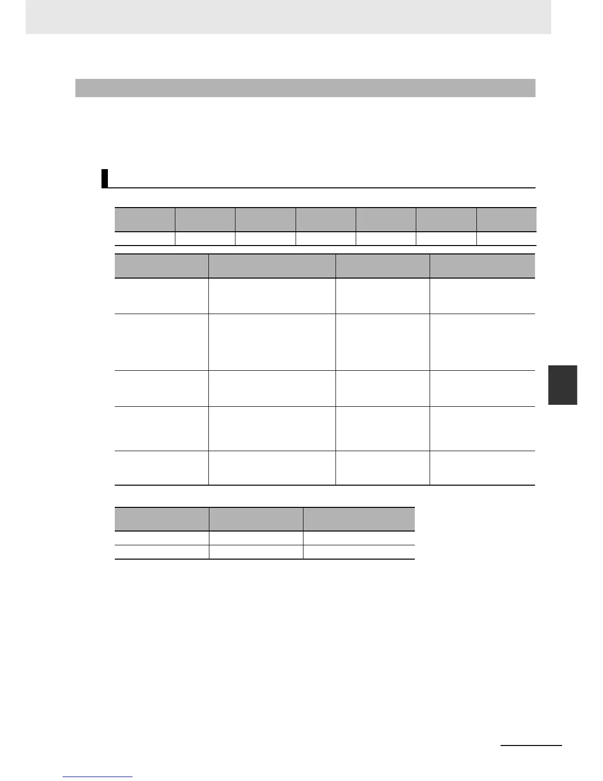
Power Supply Errors
POWER RUN ERR/ALM
CX-Program-
mer display
Error flag Error code
Error infor-
mation
Not lit. Not lit. Not lit. ---- None None None
Suspected cause of
error
Confirmation method Remedy
Prevention of recur-
rence
Power is not being
input.
Use a tester to measure the volt-
age at the input terminals of the
Power Supply Unit.
*1
Turn the power ON
again.
Investigate the reason that
the power was turned
OFF.
Connection status of
power supply selector
terminals
• 100 VAC:
Use a tester check for short-
circuits.
• 200 VAC:
Check for disconnections.
Reconnect and secure
the terminal connec-
tions.
Periodically (approxi-
mately once a year)
tighten the terminal con-
nections.
The voltage is out of
the allowable range for
the power supply.
Use a tester to measure the volt-
age at the input terminals to the
Power Supply Unit.
*1
Correct the power sup-
ply system for the PLC.
Same as at the left.
Power Supply Unit fail-
ure
Replace the Power Supply Unit
and check operation. (Check
whether the POWER indicator is
lit.)
Replace the Power
Supply Unit.
Depends on the type of
error.
Failure at another Unit Remove in order the Units
mounted in the Rack and check
the POWER indicator.
Replace the failed Unit. Depends on the type of
error.
Model Power supply voltage
Allowable power supply
voltage fluctuation
CJ1W-PA205R/PA202 100 to 240 VAC 85 to 264 VAC
CJ1W-PD025 24 VDC 19.2 to 28.8 VDC