5-25
5 Installation
CJ2 CPU Unit Hardware User’s Manual
5-3 Wiring
5
5-3-2 Wiring CJ-series Basic I/O Units with
Terminal Blocks
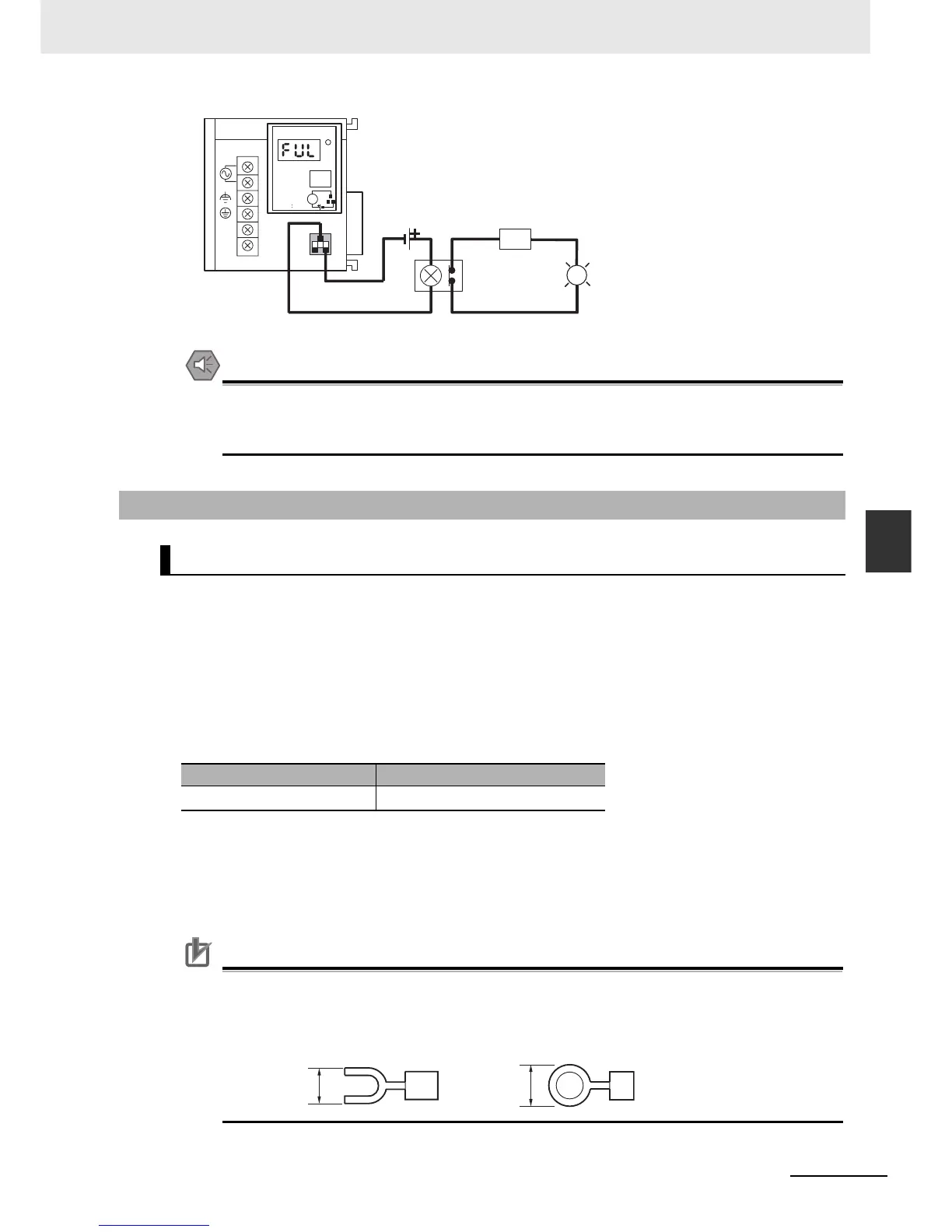
Note The OL display will also light if the PLC's power supply fails.
Precautions for Safe Use
• Separate the alarm output cables from power lines and high-voltage lines.
• Do not apply a voltage or connect a load to the alarm output that exceeds the rated voltage or
load.
z I/O Unit Specifications
Double-check the specifications for the I/O Units. In particular, do not apply a voltage that exceeds
the input voltage for Input Units or the maximum switching capacity for Output Units. Doing so may
result in breakdown, damage, or fire.
When the power supply has positive and negative terminals, be sure to wire them correctly.
z Electric Wires
• The following wire gauges are recommended.
• The current capacity of electric wire depends on factors such as the ambient temperature and
insulation thickness as well as the gauge of the conductor.
z Crimp Terminals
The terminals on the I/O Unit are M3, self-raising terminals with screws.
Precautions for Correct UsePrecautions for Correct Use
• Use crimp terminals for wiring.
• Do not connect bare stranded wires directly to terminals.
• Tighten the terminal block screws to the torque of 0.5 N·m.
• Use crimp terminals (M3) having the dimensions shown below.
5-3-2 Wiring CJ-series Basic I/O Units with Terminal Blocks
Precautions for Wiring I/O Units
Terminal Block Connector Wire Size
18-terminal
AWG 22 to 18 (0.32 to 0.82 mm
2
)
AC100-240V
INPUT
NC
NC
L1
L2/N
CJ1W-PA205C
POWER
TEST
ALARM OUTPUT
DC30V, 50mA
NORMAL:ON
ALARM OFF
L
OL
24-VDC power supply
Relay
(NC contacts)
Power
supply
6.2 mm max.
6.2 mm max.