3 Nomenclature and Functions
3-2
CJ2 CPU Unit Hardware User’s Manual
3-1 CPU Units
3-1-1 CPU Section
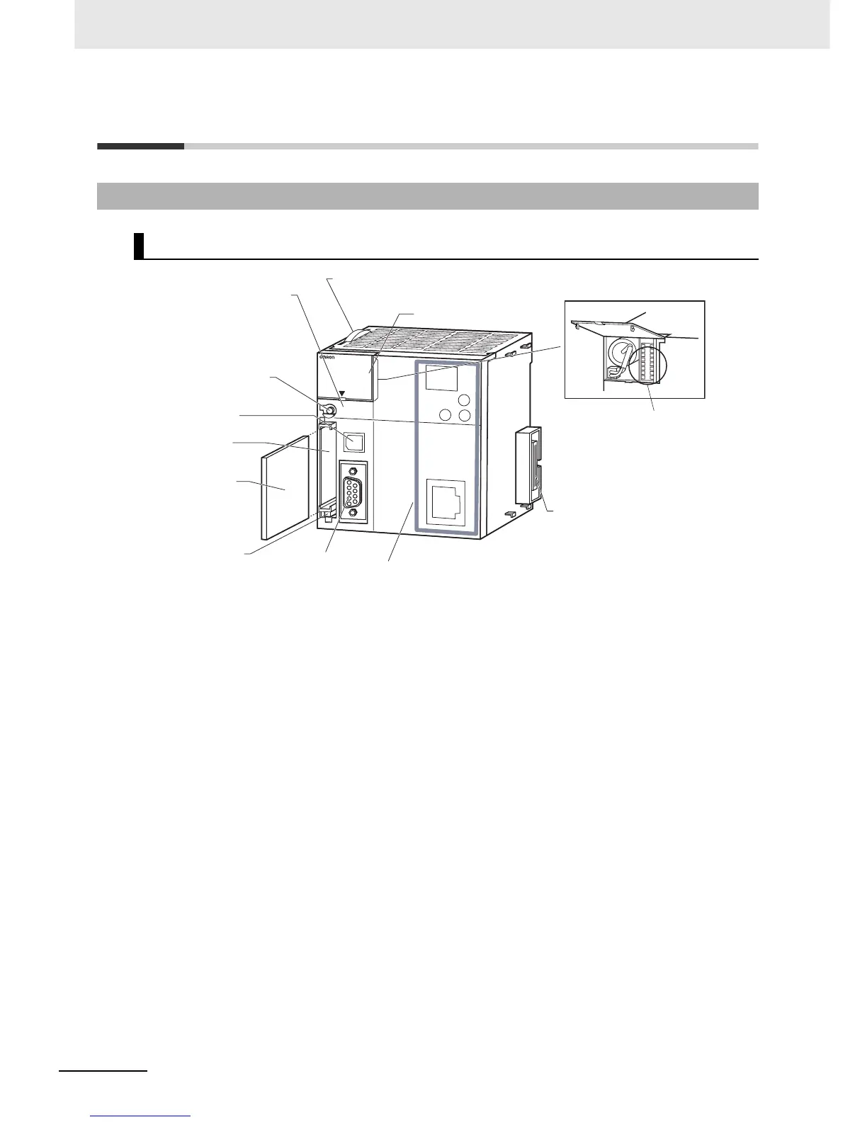
Components and Functions
1. Memory Card Indicators (Refer to 3-2 Memory Card.)
Indicates the Memory Card status (access and power
supply).
2. Simple Backup/Memory Card Power Supply Switch
(Refer to 3-2 Memory Card.)
Used to back up Memory Card data or turn OFF the
power when removing the Memory Card.
3. Peripheral (USB) Port
Connected to Programming Devices, such as the CX-
Programmer
4. Memory Card Connector (Refer to 3-2 Memory Card.)
Connects the Memory Card to the CPU Unit.
5. Memory Card (Refer to 3-2 Memory Card.)
All CPU Unit data can be copied to a Memory Card to
back up the data. If a Memory Card Adapter is used, the
Memory Card can be mounted in the PCMIA slot in a
personal computer.
6. Memory Card Eject Button (Refer to 3-2 Memory Card.)
Press the eject button to remove the Memory Card from
the CPU Unit.
7. Slider
Secures the CPU Unit to the next Unit.
8. LED Indicators (Refer to the next page.)
These indicators show the status of the CPU Unit:
• Normal operation
• Errors
• Output OFF status
• Communications status for the peripheral (USB) and RS-
232C ports
• Backup status between RAM and built-in flash memory
9. DIP Switch (Refer to a following page.)
Sets operations, such as user memory protection, auto-
matic program transfer by Memory Card, serial port com-
munications mode, and simple backup.
10. RS-232C Serial Port (Refer to A-4 Connecting to the RS-
232C Serial Port on the CPU Unit.)
Connected to Programming Devices, Host Computers,
general-purpose external devices, Programmable Termi-
nals, and other devices.
11. Connector
Connected to the next Unit.
6. Memory Card
Eject Button
5. Memory Card
4. Memory Card
Connector
8. LED Indicators
1. Memory Card Indicators
Refer to 3-1-2 Built-in EtherNet/IP Section for information
on the built-in EtherNet/IP Section.
2. Simple Backup/Memory Card
Power Supply Switch
3. Peripheral (USB)
Port
10. RS-232C Serial Port
9. DIP Switch
7. Slider
Inside the battery compartment
11. Connector
HFI
RE
PLARE
E
R
R/A LM
R
U
N
IN
H
CO
M
M
BK
U
P
PRP
HL
NS
M
S
C
OMM
10
M
10
0M
CON
T
RO
LLE
R
CPU64-EIP
CJ2H
SYSMAC
PRO
G
RAM
MABLE
PORT
OPEN
B
U
S
Y
MC
P
WR