3-3
3 Nomenclature and Functions
CJ2 CPU Unit Hardware User’s Manual
3-1 CPU Units
3
3-1-1 CPU Section
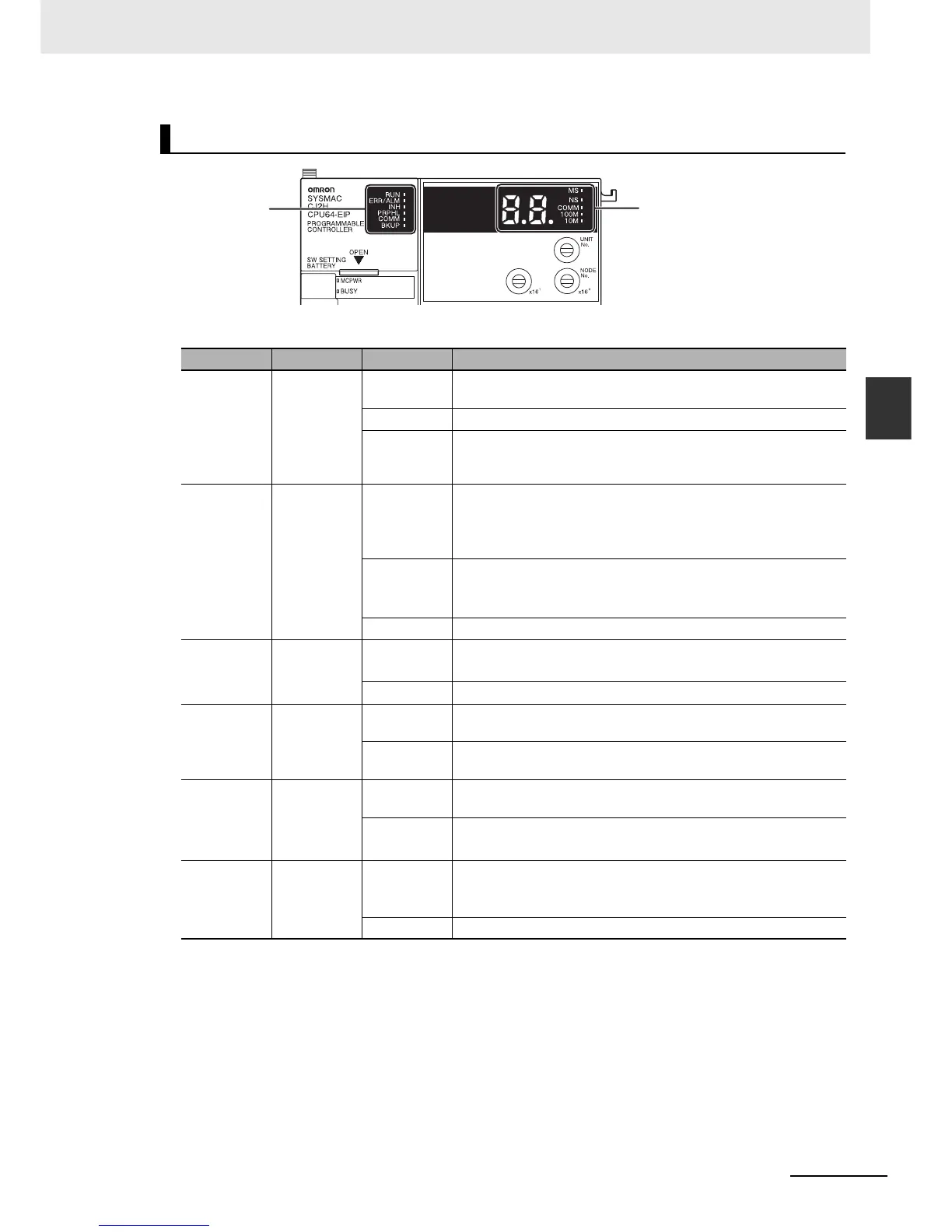
The CJ2 CPU Unit status can be checked with the indicators at the top of the front panel of the Unit.
The following table describes these indicators.
*1 Do not turn OFF the power supply to the PLC while this indicator is lit.
CPU Unit Status Indicators
Indicator Color Status Meaning
RUN Green ON Lights when the PLC is operating normally in MONITOR or RUN
mode. The program is being executed.
Flashing System download mode error or DIP switch settings error.
OFF PLC has stopped operating while in PROGRAM mode, or has
stopped operating due to a fatal error, or is downloading data from
the system.
ERR/ALM Red ON A fatal error (including FALS(007) instruction execution) or a hard-
ware error (watchdog timer error) was found in self-diagnosis.
The CJ2 CPU Unit will stop operating, and the outputs from all
Output Units will turn OFF.
Flashing A non-fatal error was found (including FAL(006) instruction execu-
tion) in the self-diagnosis.
The CJ2 CPU Unit will continue operating.
OFF The CJ2 CPU Unit is operating normally.
INH Yellow ON Output OFF Bit (A500.15) has been turned ON.
The outputs from all Output Units will turn OFF.
OFF Output OFF Bit (A500.15) has been turned OFF.
PRPHL Yellow Flashing The CJ2 CPU Unit is communicating (sending or receiving) via the
peripheral (USB) port.
OFF The CJ2 CPU Unit is not communicating via the peripheral (USB)
port.
COMM Yellow Flashing The CJ2 CPU Unit is communicating (sending or receiving) via the
serial port (RS-232C).
OFF The CJ2 CPU Unit is not communicating via the serial port
(RS-232C).
BKUP Yellow ON User program and parameter area data is being backed up to
flash memory in the CPU Unit or being restored from flash mem-
ory after the power supply to the PLC was turned ON.
*1
OFF Data is not being written to flash memory.
Indicators on front
of CPU Unit
7-segment display and
indicators for
EtherNet/IP port
(Refer to 3-1-2
Built-in EtherNet/IP Section.)