5-17
5 Installation
CJ2 CPU Unit Hardware User’s Manual
5-2 Installation
5
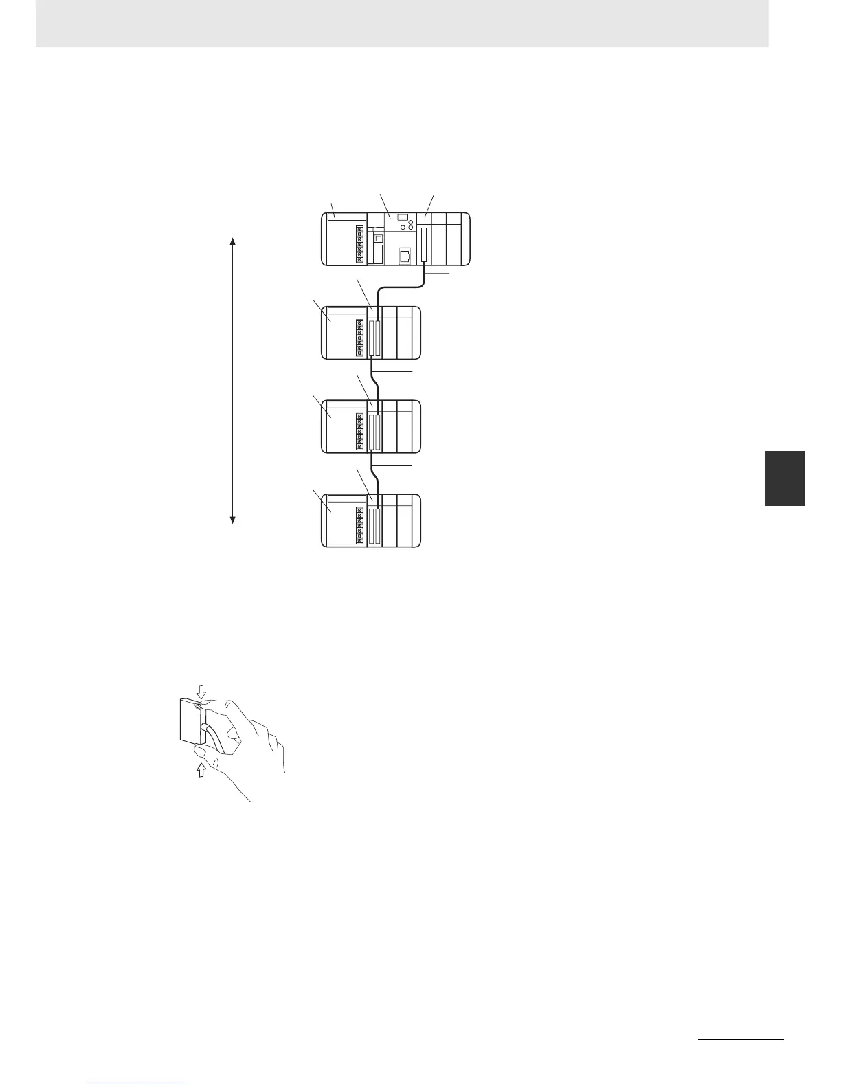
5-2-6 Connecting CJ-series Expansion Racks
z Cable Connections
The following diagram shows examples of proper Rack connections. Connect the simple lock con-
nectors to the I/O Control Unit on the CJ-series CPU Rack and the I/O Interface Unit on the CJ-
series Expansion Rack.
• The top and bottom of the connector are different. Be sure the connector is facing the correct
direction before connecting it.
z Connecting the Simple Locking Connectors
Press the tabs on the end of the connector and insert the connector until it locks in place. The PLC
will not operate properly if the connector isn’t inserted completely.
To remove the connector, press the tabs and pull on the connector.
Power
Supply Unit
CPU Unit
I/O Control Unit
I/O Interface Unit
Power Supply Unit
CPU Rack
Expansion Rack
Expansion Rack
I/O Connecting Cable
I/O Connecting Cable
I/O Interface Unit
Power Supply Unit
I/O Interface Unit
Power Supply Unit
Expansion Rack
I/O Connecting Cable
Total cable
length:
12 m max.