A-51
Appendices
CJ2 CPU Unit Hardware User’s Manual
A-1 Specifications of Basic I/O Units
App
A-1-3 Precautions on Contact Output Units
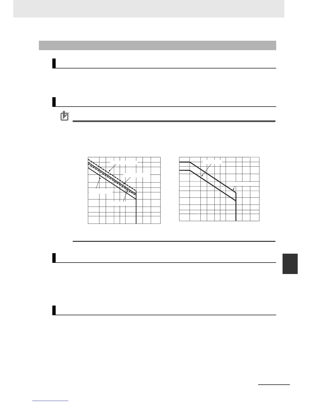
The service life expectancy of the relays (NY-24W-K-IE) in the CJ1W-OC201/211 Contact Output
Units is shown in the following diagrams. Use the diagrams to calculate the relay service life based
on the operating conditions, and replace the relay before the end of its service life.
Precautions for Correct UsePrecautions for Correct Use
The diagrams show the life expectancy of the relay itself. Do not use a contact current, therefore,
that exceeds the maximum switching capacity specified in the specifications for each Contact
Output Unit. If a switching capacity exceeding the specifications is used, the reliability and life
expectancy of other parts will be reduced and the Unit may malfunction.
The life of the Relay varies with the load inductance. If any inductive load is connected to the Con-
tact Output Unit, use an arc killer with the Contact Output Unit using an inductive load. (See next
page.)
Be sure to connect a diode in parallel with every DC inductive load that is connected to the Contact
Output Unit.
Arc killers are used with the Contact Output Unit in order to prolong the life of each Relay mounted
to the Contact Output Unit, prevent noise, and reduce the generation of carbide and nitrate deposits.
Arc killers can, however, reduce relay life if not use correctly.
Arc killers are used with the Contact Output Unit in order to prolong the life of each Relay mounted
to the Contact Output Unit, prevent noise, and reduce the generation of carbide and nitrate deposits.
Arc killers can, however, reduce relay life if not used correctly.
A-1-3 Precautions on Contact Output Units
Service Life Expectancy of CJ1W-OC201/211 Relays
Contact Current vs. Service Life Characteristic
Inductive Load
Contact Protection Circuit
0.1 0.2 0.3 0.5 1 2 3 50.7
2
3
5
10
20
30
50
100
200
300
0.1 0.2 0.3 0.5 1 2 3 5 0.7
2
3
5
10
20
30
50
100
200
300
0.05
Service Life with AC Load
Service Life with DC Load
120 VAC, resistive load
240 VAC, resistive load
120 VAC cos f = 0.4
240 VAC cos
φ
= 0.4
Service life (x10
4
)
Service life (x10
4
)
Contact current (A)
Contact current (A)
24 VDC, resistive load
24 VDC
τ
= 7 ms
Switching frequency: 1,800 operations/hour max.