5-19
5 Installation
CJ2 CPU Unit Hardware User’s Manual
5-3 Wiring
5
5-3-1 Power Supply Wiring
5-3 Wiring
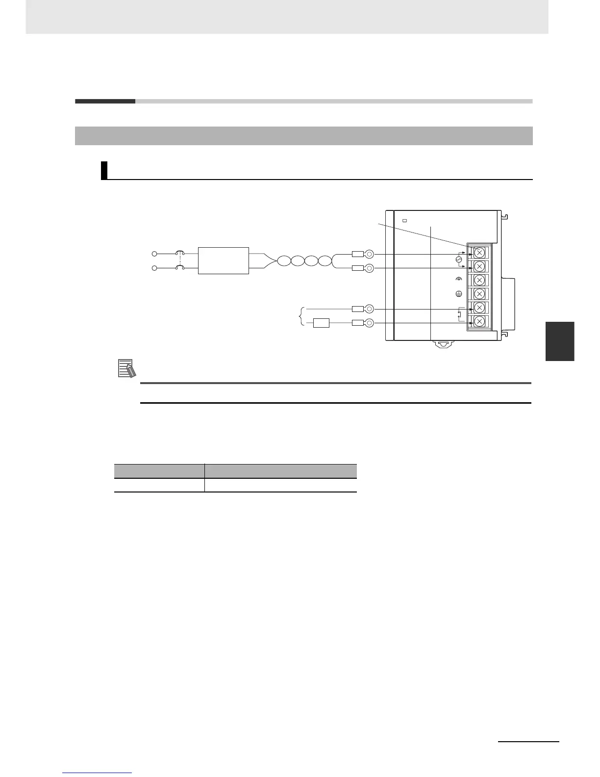
z CJ1W-PA205R Power Supply Unit
Additional Information
The RUN output function is enabled only when mounted to a CPU Rack.
z AC Power Source
• Supply 100 to 240 VAC.
• Keep voltage fluctuations within the specified range:
• If one power supply phase of the equipment is grounded, connect the grounded phase side to the
L2/N terminal.
z Isolation Transformer
The PLC's internal noise isolation circuits are sufficient to control typical noise in power supply lines,
but noise between the PLC and ground can be significantly reduced by connecting a 1-to-1 isolation
transformer. Do not ground the secondary coil of the transformer.
z Power Supply Capacity
The power consumption will be 100 VA max. per Rack for the CJ1W-PA205R/PA205C and 50 VA for
the CJ1W-PA202, but there will be a surge current of at least 5 times the max. current when power is
turned ON.
z RUN Output
The RUN output is provided only on the CJ1W-PA25R Power Supply Unit. This output is ON when-
ever the CPU Unit is operating in RUN or MONITOR mode; it is OFF when the CPU Unit is in PRO-
GRAM mode or a fatal error has occurred (including execution of the FALS(007) instruction).
5-3-1 Power Supply Wiring
AC Power Supply Units
Supply voltage Allowable voltage fluctuations
100 to 240 VAC 85 to 264 VAC
POWER
PA205R
DC24V
AC240V
OUTPUT
RUN
INPUT
AC100-240V
L2/N
L1
Isolation
transformer
1:1
AC power supply
100 to 240 V
AC power supply
M4 self-raising screw terminals
Power
supply
RUN output
ON when CPU Unit is in RUN or
MONITOR mode.
OFF when CPU Unit is in
PROGRAM mode or stopped for
a fatal error.