A-119
Appendices
CJ2 CPU Unit Hardware User’s Manual
A-7 Relay Output Noise Reduction Methods
App
A-7 Relay Output Noise Reduction
Methods
The CJ-series PLCs conforms to the Common Emission Standards (EN61000-6-4) of the EMC Direc-
tives. However, noise generated by relay output switching may not satisfy these Standards. In such a
case, a noise filter must be connected to the load side or other appropriate countermeasures must be
provided external to the PLC.
Countermeasures taken to satisfy the standards vary depending on the devices on the load side, wir-
ing, configuration of machines, etc. Following are examples of countermeasures for reducing the gener-
ated noise.
(Refer to EN61000-6-4 for more details.)
Countermeasures are not required if the frequency of load switching for the whole system with the PLC
included is less than 5 times per minute.
Countermeasures are required if the frequency of load switching for the whole system with the PLC
included is more than 5 times per minute.
When switching an inductive load, connect an surge protector, diodes, etc., in parallel with the load or
contact as shown below.
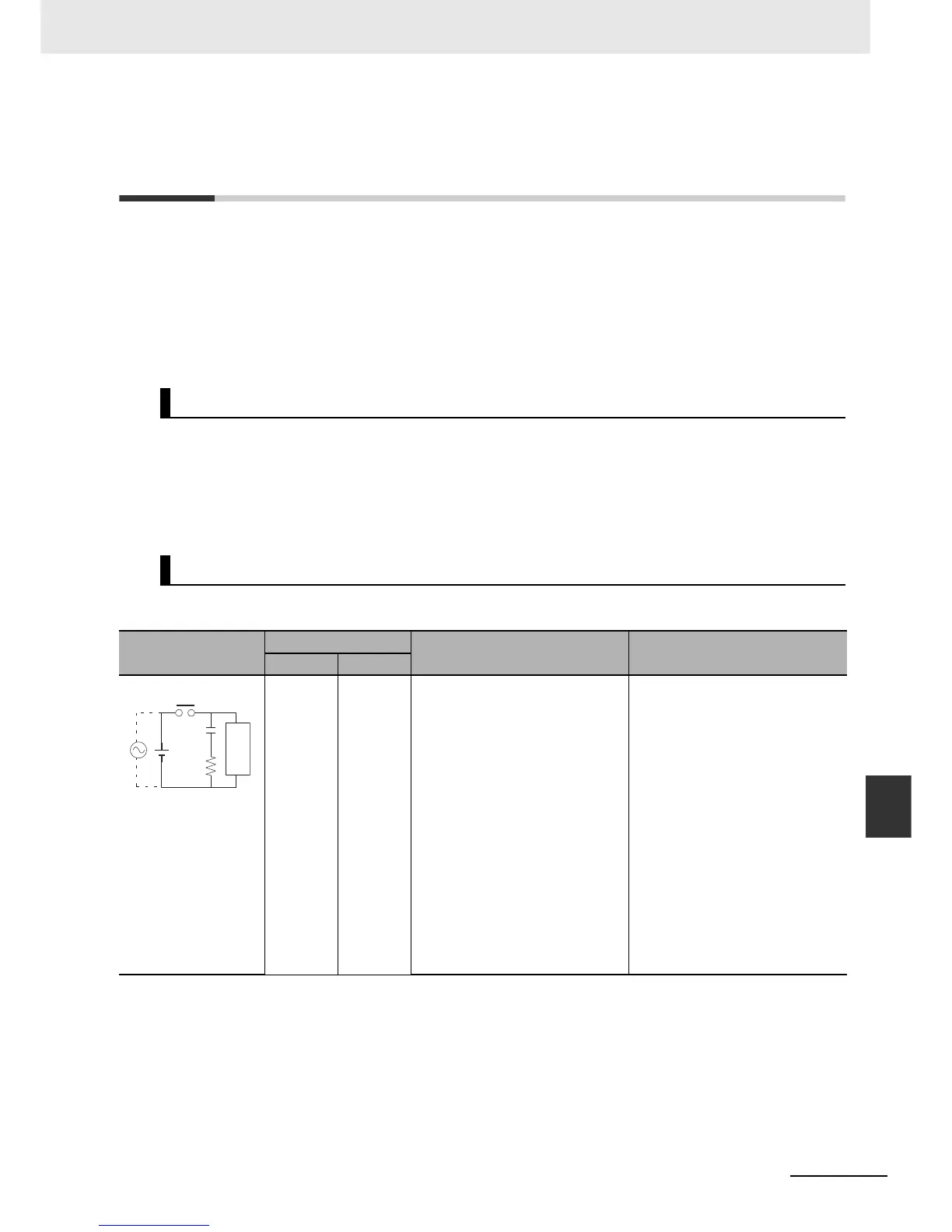
Countermeasures
Countermeasure Examples
Circuit
Current
Characteristic Required element
AC DC
Yes Yes If the load is a relay or solenoid,
there is a time lag between the
moment the circuit is opened and
the moment the load is reset.
If the supply voltage is 24 or 48 V,
insert the surge protector in parallel
with the load. If the supply voltage
is 100 to 200 V, insert the surge
protector between the contacts.
The capacitance of the capacitor
must be 1 to 0.5 µF per contact cur-
rent of 1 A and resistance of the
resistor must be 0.5 to 1 Ω per con-
tact voltage of 1 V. These values,
however, vary with the load and the
characteristics of the relay. Decide
these values from experiments, and
take into consideration that the
capacitance suppresses spark dis-
charge when the contacts are sep-
arated and the resistance limits the
current that flows into the load
when the circuit is closed again.
The dielectric strength of the
capacitor must be 200 to 300 V. If
the circuit is an AC circuit, use a
capacitor with no polarity.
CR method
Power
supply
Inductive
load
C
R