Appendices
A-52
CJ2 CPU Unit Hardware User’s Manual
Precautions for Correct UsePrecautions for Correct Use
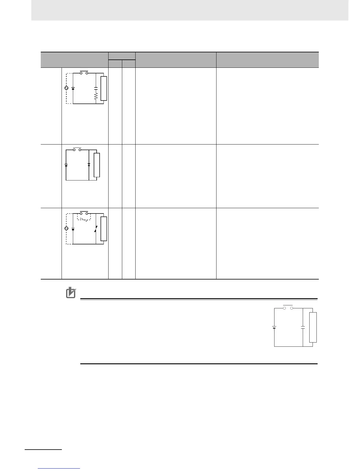
Do not connect a capacitor as an arc killer in parallel with an inductive load
as shown in the following diagram. This arc killer is very effective for pre-
venting spark discharge at the moment when the circuit is opened. How-
ever, when the contacts are closed, the contacts may be welded due to the
current charged in the capacitor.
DC inductive loads can be more difficult to switch than resistive loads. If
appropriate arc killers are used, however, DC inductive loads will be as easy
to switch as resistive loads.
Circuit
Current
Characteristic Required element
AC DC
CR
method
Yes Yes If the load is a relay or solenoid, there
is a time lag between the moment the
circuit is opened and the moment the
load is reset.
If the supply voltage is 24 or 48 V,
insert the arc killer in parallel with the
load. If the supply voltage is 100 to
200 V, insert the arc killer between the
contacts.
The capacitance of the capacitor must be 1 to
0.5 µF per contact current of 1 A and resistance
of the resistor must be 0.5 to 1 Ω per contact volt-
age of 1 V. These values, however, vary with the
load and the characteristics of the relay. Decide
these values from experiments, and take into con-
sideration that the capacitance suppresses spark
discharge when the contacts are separated and
the resistance limits the current that flows into the
load when the circuit is closed again.
The dielectric strength of the capacitor must be
200 to 300 V. If the circuit is an AC circuit, use a
capacitor with no polarity.
Diode
method
No Yes The diode connected in parallel with
the load changes energy accumulated
by the coil into a current, which then
flows into the coil so that the current
will be converted into Joule heat by the
resistance of the inductive load. This
time lag, between the moment the cir-
cuit is opened and the moment the
load is reset, caused by this method is
longer than that caused by the CR
method.
The reversed dielectric strength value of the
diode must be at least 10 times as large as the
circuit voltage value. The forward current of the
diode must be the same as or larger than the load
current.
The reversed dielectric strength value of the
diode may be two to three times larger than the
supply voltage if the arc killer is applied to elec-
tronic circuits with low circuit voltages.
Varistor
method
Yes Yes The varistor method prevents the
imposition of high voltage between the
contacts by using the constant voltage
characteristic of the varistor. There is
time lag between the moment the cir-
cuit is opened and the moment the
load is reset.
If the supply voltage is 24 or 48 V,
insert the varistor in parallel with the
load. If the supply voltage is 100 to
200 V, insert the varistor between the
contacts.
---
Power
supply
Inductive load
C
R
Power
supply
Inductive load
Power
supply
Inductive load
C
Power
supply
Inductive load