5 Installation
5-24
CJ2 CPU Unit Hardware User’s Manual
z Wiring
The following wire gauges are recommended.
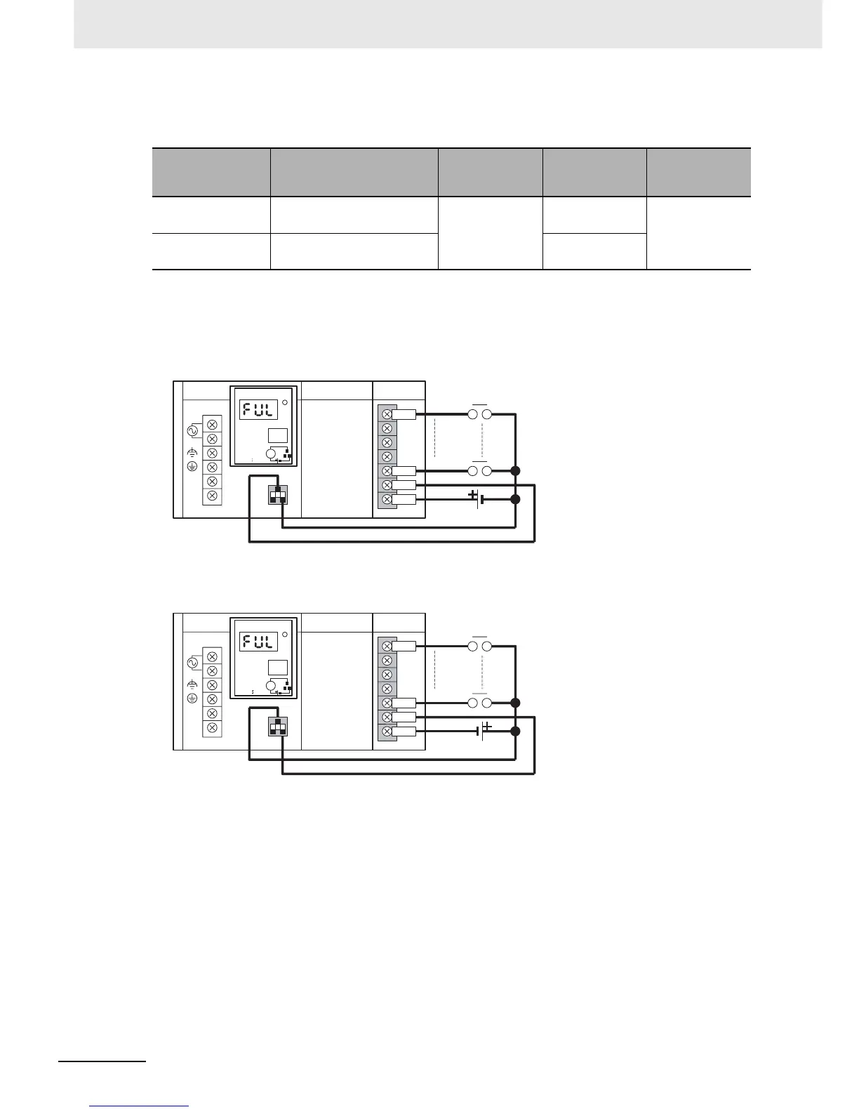
z PLC Input Unit Wiring Example
Connect the positive terminals of the 24-VDC power supply to the Input Unit common (COM) termi-
nals.
Connect the negative terminal of the 24-VDC power supply to the Input Unit common (COM) termi-
nal.
z External Display Device Connection Example
The alarm output (replacement notification output) is an NC contact. Therefore, wire the alarm out-
put using an NC contact or other means to turn ON an error indicator or LED display as shown in the
following diagram.
Recommended
wire size
Use
Pushing
strength (clamp-
ing operation)
Pulling strength
(holding force)
Length of
stripped section
AWG 22 to 18
(0.32 to 0.82 mm
2
)
Connecting to PLC terminal
block models
30 N max. 30 N min. 7 to 10 mm
AWG 28 to 24
(0.08 to 0.2 mm
2
)
Connecting to PLC connector
models
10 N min.
AC100-240V
INPUT
NC
NC
L1
L2/N
CJ1W-PA205C
POWER
TEST
ALARM OUTPUT
DC30V, 50mA
NORMAL:ON
ALARM OFF
L
IN0
IN(N)
IN(N+1)
COM
CPU Unit
CJ1W-PA205C
IN Unit
CJ1W-ID2@@
24-VDC power supply
IN0
IN(N)
IN(N+1)
COM
AC100-240V
INPUT
NC
NC
L1
L2/N
CJ1W-PA205C
POWER
TEST
ALARM OUTPUT
DC30V, 50mA
NORMAL:ON
ALARM OFF
L
CJ1W-PA205C CPU Unit
IN Unit
CJ1W-ID2@@
24-VDC power supply