5 Installation
5-26
CJ2 CPU Unit Hardware User’s Manual
z Wiring
• Make sure that all Units are connected properly.
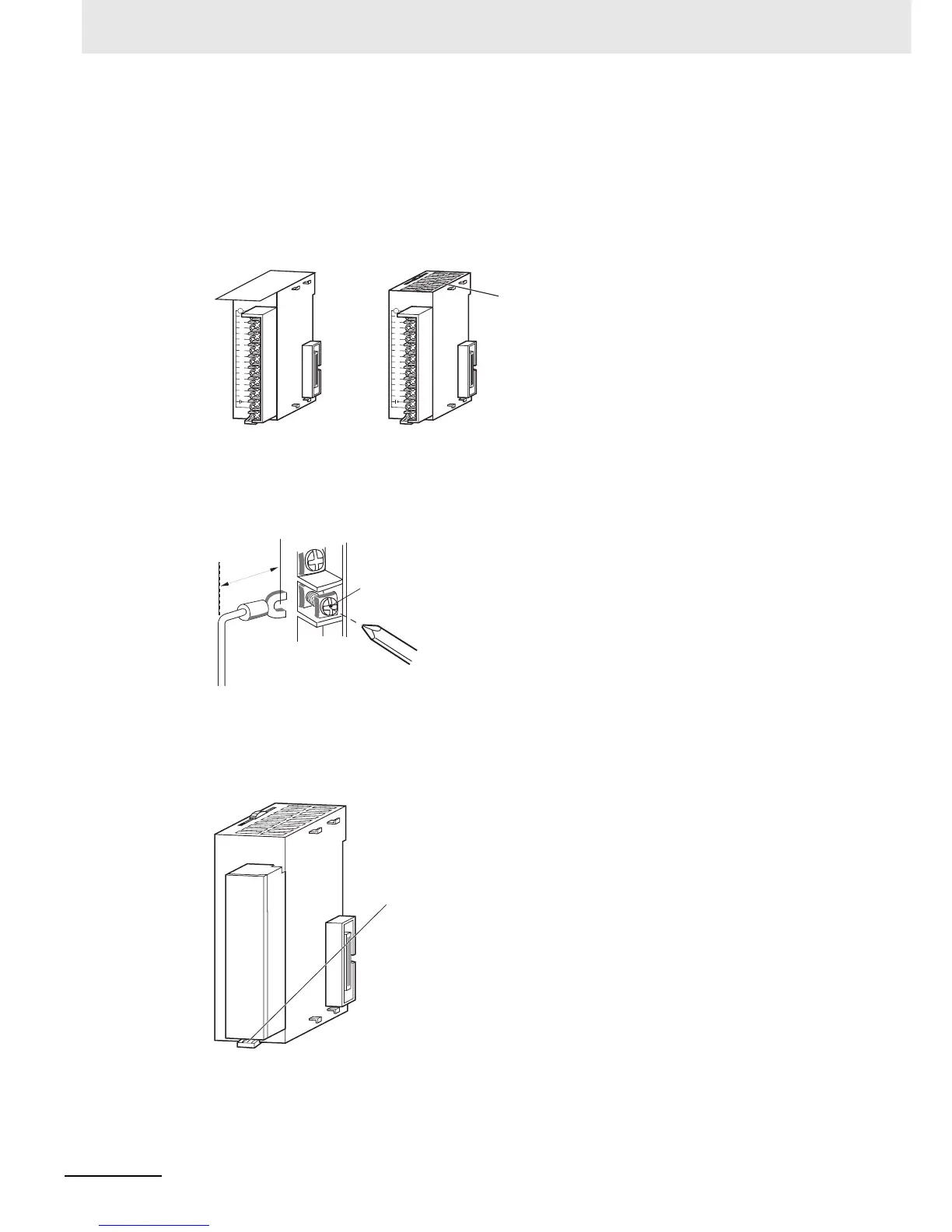
• Do not remove the protective label from the top of the Unit until wiring has been completed.
• This label prevents wire strands and other foreign matter from entering the Unit during wiring pro-
cedures.
• Remove the label after wiring has been completed to allow air circulation needed for cooling.
• Wire the Units so that they can be easily replaced.
• Make sure that the I/O indicators are not covered by the wiring.
• Do not place the wiring for I/O Units in the same duct or raceway as power lines. Inductive noise
can cause errors in operation.
• Tighten the terminal screws to the torque of 0.5 N·m.
z Terminal Blocks
• The I/O Units are equipped with removable terminal blocks. The lead wires do not have to be
removed from the terminal block to remove it from an I/O Unit.
• After you complete wiring, check to see if the terminal block is securely locked.
O
D211
0
123
4
5
6
7
8 9 10 11 12 13 14 15
OD
211
01
234
567
8
9 10 11 12 13 14 15
After wiringDuring wiring
Remove the label.
17.5 mm
Screw (M3 screw with
self-raising pressure plate)
112D
O
012
3
45
67
8 9 10 11 12 13 14 15
Terminal block lever
CJ-series Basic I/O Unit