Appendices
A-72
CJ2 CPU Unit Hardware User’s Manual
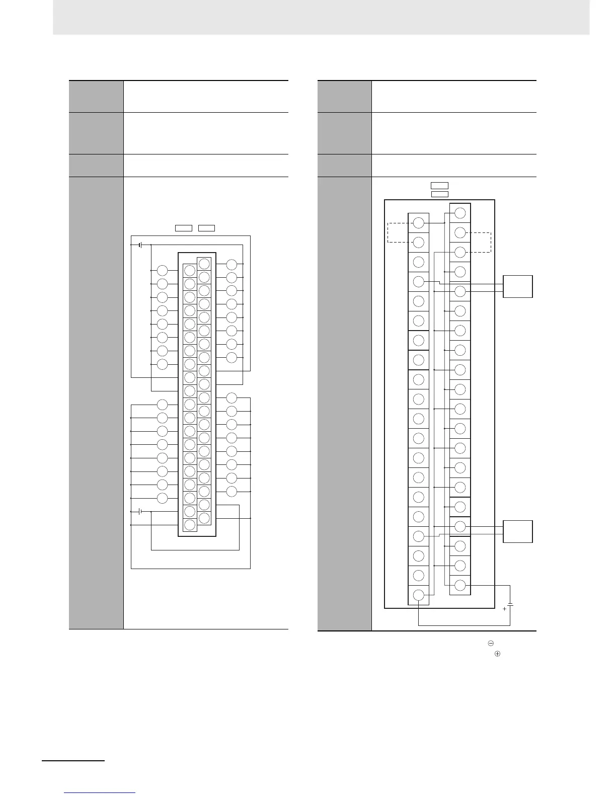
Note The +V terminals and COM terminals are internally
connected inside the PLC, but they must all be wired.
Note 1 Connect the A9/B9 terminal and the terminal.
Connect the A10/B10 terminal and the terminal.
(Use the enclosed short bar.)
2 The COM terminals are wired inside the Connec-
tor-Terminal Block Conversion Unit.
Programma-
ble Control-
ler I/O Unit
CJ1W-OD263
Connector-
Terminal
Block Con-
version Unit
XW2D-40G6
Connecting
Cables
XW2Z-@@@K
Connection
diagram
12 to
24 VDC
12 to
24 VDC
11
10
12
13
14
15
10
11
12
13
14
15
03
02
09
01
08
00
04
05
06
07
02
09
01
08
00
03
04
05
06
07
L
L
L
L
L
L
L
L
L
L
L
L
L
L
L
L
L
L
L
L
L
L
L
L
L
L
L
L
L
L
L
L
COM0
COM0
COM1
COM1
CN1
A20
A11
A12
A13
A14
A15
A16
A17
A18
A19
B20
B11
B12
B13
B14
B15
B16
B17
B18
B19
A10
A1
A2
A3
A4
A5
A6
A7
A8
A9
B10
B1
B2
B3
B4
B5
B6
B7
B8
B9
()
Wd m
(Wd (m+2))
CN2
(COM2)
(COM2)
+V
+V
(COM3)
+V
Wd (m+1)
(Wd (m + 3))
(COM3)
+V
Programma-
ble Control-
ler I/O Unit
CJ1W-OD263
Connector-
Terminal
Block Con-
version Unit
XW2C-20G6-IO16 (2 Units)
Connecting
Cables
XW2Z-@@@N
Connection
diagram
0
1
2
3
4
5
6
7
8
9
10
11
12
13
14
15
A9
B9
A10
B10
CN1
COM0
15
14
13
12
11
10
09
08
07
06
05
04
03
02
01
00
12 to
24 VDC
Solenoid valve, etc.
(Short bar)
Wd m
and (m+1)
(Wd (m+2)
and (m+3))
(Short bar)
+V
(COM1)
()
CN2
Solenoid valve, etc.
−
+
−
+
+
−
+
−
+
−
+
−
+
−
+
−
+
−
+
+
−
−