5-3
5 Installation
CJ2 CPU Unit Hardware User’s Manual
5-1 Fail-safe Circuits
5
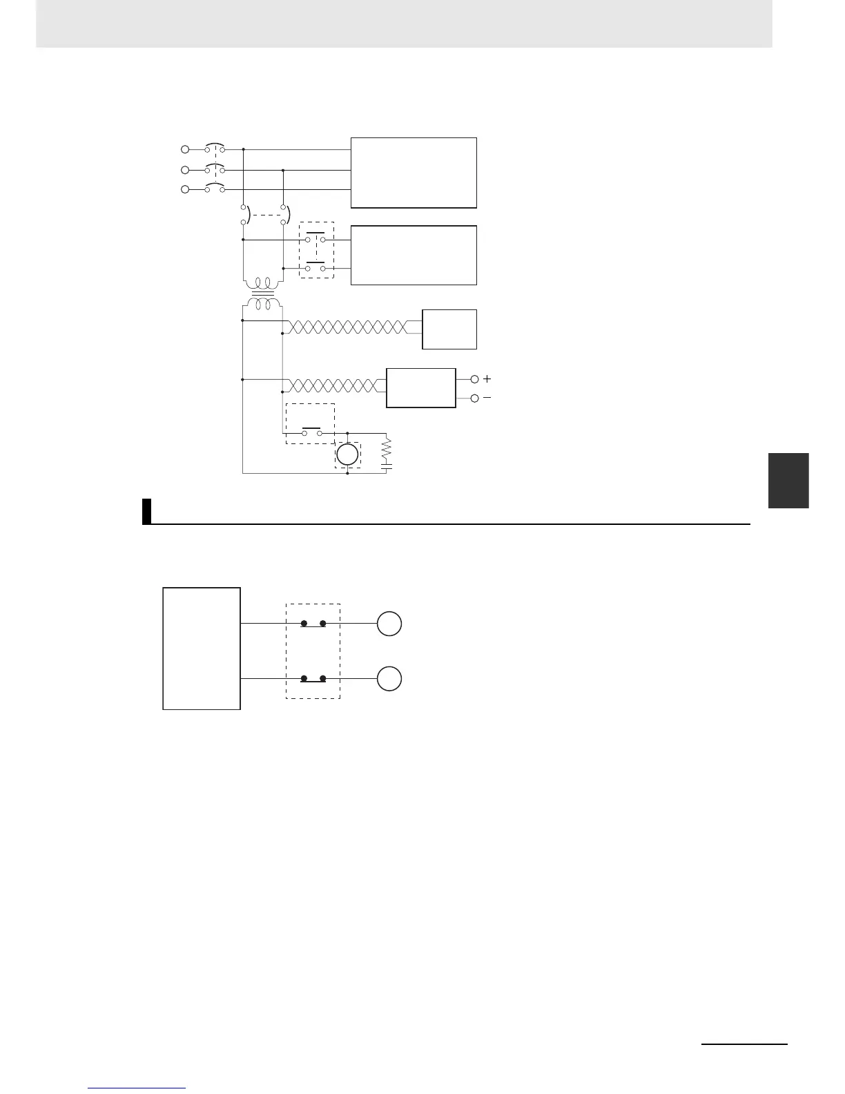
z Electrical Diagram
When the PLC controls an operation such as the clockwise and counterclockwise operation of a motor,
provide an external interlock such as the one shown in the following example to prevent both the for-
ward and reverse outputs from turning ON at the same time.
This circuit prevents outputs MC1 and MC2 from both being ON at the same time even if both
CIO 000501 and CIO 000502 are ON, so the motor is protected even if the PLC is programmed improp-
erly or malfunctions.
Interlock Circuits
MCB1
MCB2
CR1
CR1
DC
PLC RUN
output
input/output
Power supply
Controlled system
DC voltage
regulator
Surge suppressor
Twisted-pair wires
Transformer
or noise filter
CJ-series
PLC
CJ-series
PLC
MC2
000501
MC1
000502
MC1
MC2
Interlock circuit
Motor clockwise
Motor counterclockwise