5 Installation
5-12
CJ2 CPU Unit Hardware User’s Manual
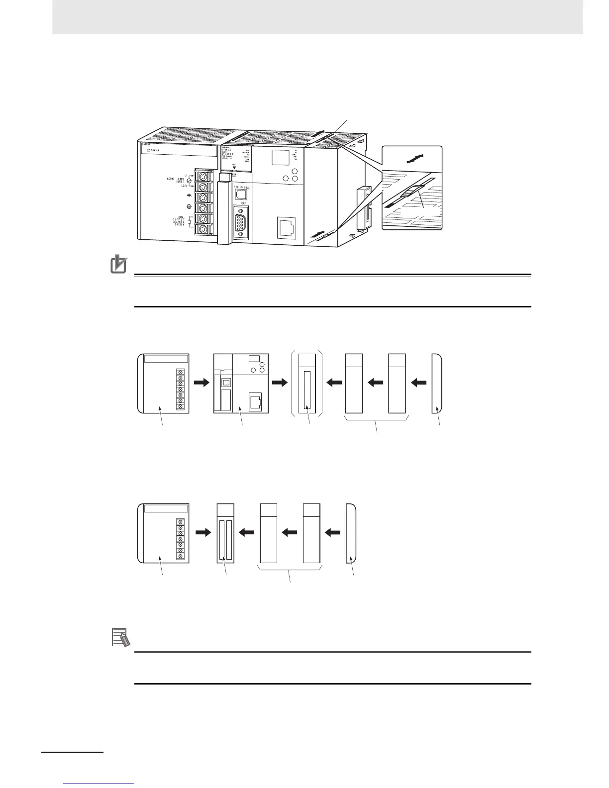
2. The yellow sliders at the top and bottom of each Unit lock the Units together. Move the sliders
toward the back of the Units as shown below until they click into place.
Precautions for Correct UsePrecautions for Correct Use
If the locking tabs are not secured properly, the connectors may become loose and not function
properly. Be sure to slide the locking tabs until they are securely in place.
3. Attach the End Cover to the Unit on the far right side of the Rack.
Additional Information
There is no Backplane for the CJ-series. The PLC is constructed by connecting Units together
using the connectors on the sides.
Slider
Lock
Release
Move the sliders toward the back
until they lock into place.
CPU Rack
Power Supply
Unit
CPU Unit
(I/O Control Unit) *1
I/O Units (10 max.)
End Cover
(included with CPU Unit)
*1: Connect the I/O Control Unit directly to the CPU Unit to enable connecting Expansion
Racks.
*2: Connect the I/O Interface Unit directly to the Power Supply Unit.
Expansion Rack
I/O Interface Unit *2
I/O Units (10 max.)
End Cover
(included with
I/O Interface Unit)
Power Supply
Unit