5-33
5 Installation
CJ2 CPU Unit Hardware User’s Manual
5-3 Wiring
5
5-3-5 Connecting I/O Devices
z AC Input Units
Precautions for Safe Use
When using a reed switch as the input contact for an AC Input Unit, use a switch with an allow-
able current of 1 A or greater. If reed switches with smaller allowable currents are used, the con-
tacts may fuse due to surge currents.
z Precautions when Connecting a Two-wire DC Sensor
When using a two-wire sensor with a 12-VDC or 24-VDC input device, check that the following con-
ditions have been met. Failure to meet these conditions may result in operating errors.
• Relation between voltage when the PLC is ON and the sensor residual voltage:
V
ON
≤ V
CC
− V
R
• Relation between voltage when the PLC is ON and sensor control output (load current):
I
OUT
(min) ≤ I
ON
≤ I
OUT
(max.)
I
ON
= (V
CC
− V
R
− 1.5 [PLC internal residual voltage])/R
IN
When I
ON
is smaller than I
OUT
(min), connect a bleeder resistor R. The bleeder resistor constant
can be calculated as follows:
R ≤ (V
CC
− V
R
)/(I
OUT
(min.) − I
ON
)
Power W ≥ (V
CC
− V
R
)
2
/R × 4 [allowable margin]
V
CC
: Power voltage
V
R
: Sensor output residual current
I
ON
: PLC ON current
I
OUT
: Sensor control current (load current)
R
IN
: PLC input impedance
COM
IN
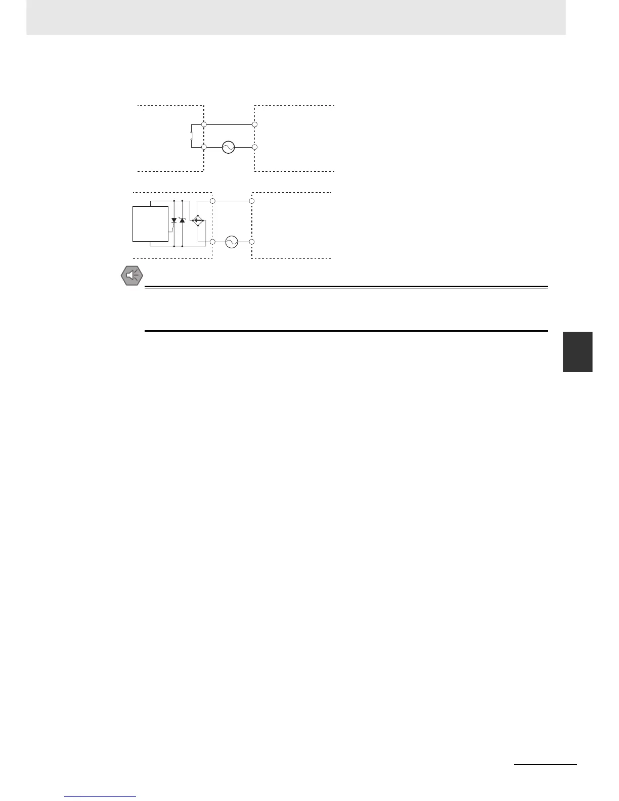
AC Input Unit
Contact output
AC Switching
Proximity
switch
main
circuit
COM
IN
AC Input Unit