8-9
8 Backup Operations
CJ2 CPU Unit Hardware User’s Manual
8-3 Simple Backup
8
8-3-2 Operating Procedures
Additional Information
• When the backup files are read from the Memory Card by the backup function, the status of
I/O memory and force-set/force-reset bits will be cleared unless the necessary settings are
made in the Auxiliary Area and PLC Setup.
If the IOM Hold Bit (A500.12) is ON and the PLC Setup is set to maintain the IOM Hold Bit Sta-
tus at Startup when the backup files are written, the status of I/O memory data will be main-
tained when data is read from the Memory Card.
If the Forced Status Hold Bit (A500.13) is ON and the PLC Setup is set to maintain the Forced
Status Hold Bit Status at Startup when the backup files are written, the status of force-set and
force-reset bits will be maintained when data is read from the Memory Card.
• After the simple backup operation has been used to restore data from the Memory Card to the
PLC, the operating mode will remain in PROGRAM mode and cannot be changed to MONI-
TOR or RUN mode until the PLC power is turned OFF. After restoring the data, turn OFF the
power, change the setting of DIP switch pin 7, and then turn the power back ON.
• File backups may take from several seconds to several minutes. For information on execution
times refer to 8-3-5 Time Required for Simple Backup.
1. Insert the Memory Card containing the backup files into the CPU Unit.
The MCPWR indicator will light and the BUSY indicator will flash and then turn OFF.
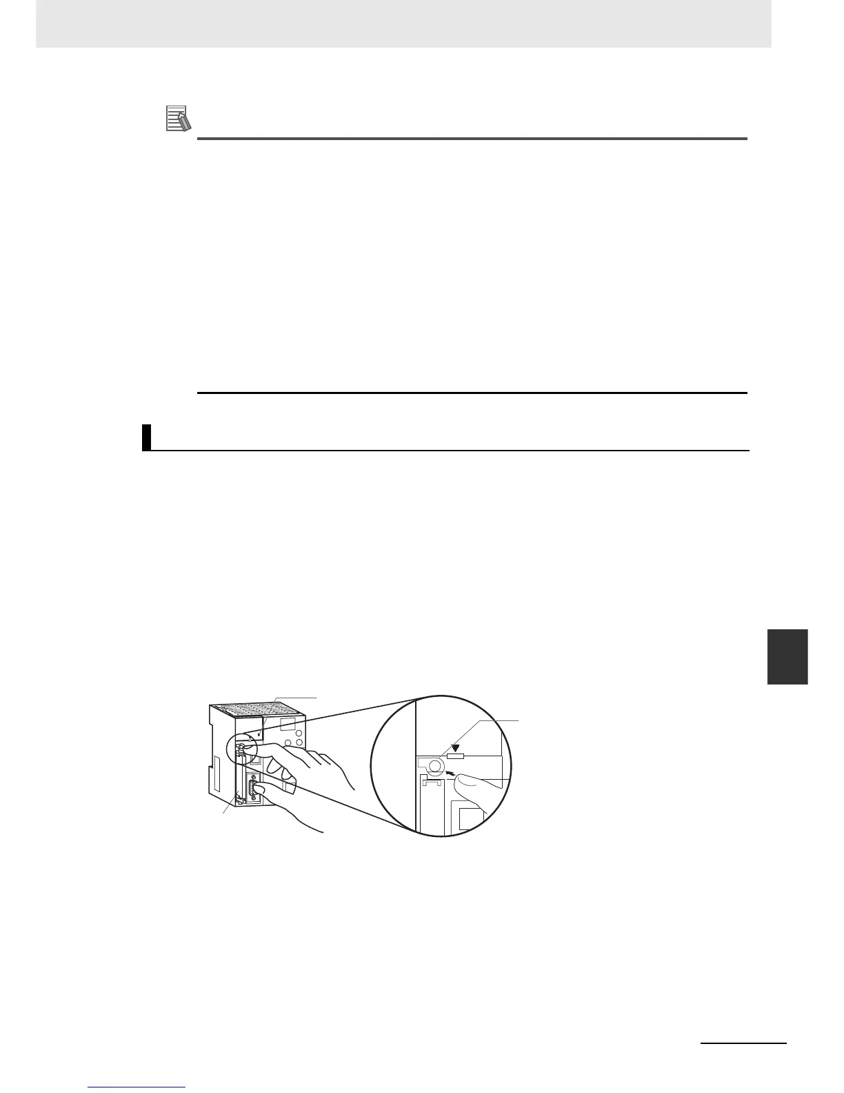
2. Turn OFF pin 7 on the CPU Unit's DIP switch.
3. Press the Memory Card Power Switch for three seconds until the BUSY indicator lights, and then
release the switch.
The PLC will start comparing the data in the PLC and the data in the backup file on the Memory
Card. The MCPWR indicator will flash once and then light while the data is being written. At the
same time the BUSY indicator will flash.
The MCPWR and BUSY indicators will both turn OFF if the data matches. If the MCPWR and
BUSY indicators both flash, it means that the data does not match or that an error has occurred.
(Refer to 8-3-3 Verifying Backup Operations with Indicators.)
Note If an error occurs during writing or comparison, the MCPWR indicator will flash. Press the power switch to
stop the flashing and to turn ON the MCPWR indicator.
Comparing Data in the Memory Card and CPU Unit
Memory Card
Press the Memory
Card Power Switch
for three seconds.
Pin 7: OFF