Appendices
A-104
CJ2 CPU Unit Hardware User’s Manual
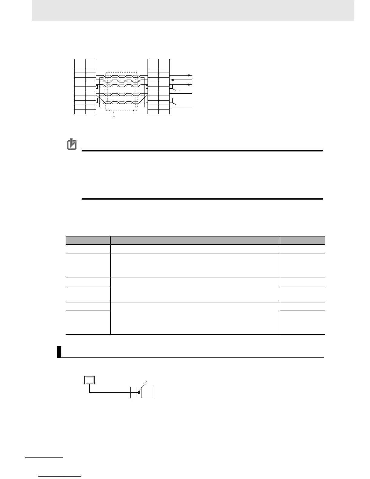
Wiring with XW2Z-@@0T-1 (10 conductors)
*2 When the NT-AL001-E Link Adapter is connected to the RS-232C port on the CPU Unit, 5 V is supplied from
pin 6, eliminating the need for a 5-V power supply.
Precautions for Correct UsePrecautions for Correct Use
• Do not use the 5-V power from pin 6 of the RS-232C port for anything but the NT-AL001-E Link
Adapter. Using this power supply for any other external device may damage the CPU Unit or
the external device.
• The XW1Z-@@0T-1 Cable is designed to connect the NT-AL001-E and contains special wiring
for the CS and RS signals. Do not use this cable for any other application. Connecting this
cable to other devices can damage them.
DIP Switch Settings on the NT-AL001-E Link Adapter
There is a DIP switch on the NT-AL001-E Link Adapter that is used to set RS-422A/485 communica-
tions parameters. Set the DIP switch as required for the serial communications mode according to the
following table.
z Direct Connection from RS-232C to RS-232C
Pin Function Default setting
1 Not used. (Leave set to ON.) ON
2 Internal terminating resistance setting.
ON: Terminating resistance connected.
OFF: Terminating resistance not connected.
ON
3 2-wire/4-wire setting
Both pins ON: 2-wire communications
Both pins OFF: 4-wire communications
OFF
4 OFF
5 Communications mode
Both pins OFF: Always send.
5 OFF/6 ON: Send when RS-232C's CS is high.
5 ON/6 OFF: Send when RS-232C's CS is low.
ON
6 OFF
Connection Example to Programmable Terminal (PT)
Shell
Not
used.
Shield
Shell
Signal
name
Signal
name
Internal signals
Arrows indicate signal directions
Returned
Returned
Pin
No.
Pin
No.
PLC
NT-AL001
1
2
3
4
5
6
7
8
9
FG
SD
RD
RS
CS
5V
DR
ER
SG
FG
1
3
2
4
5
6
7
8
9
RD
SD
RS
CS
5V
DR
ER
SG
FG
RS-232C
PT
Host Link or NT Link (1:N)
RS-232C port