2-3
2 Basic System Configuration and Devices
CJ2 CPU Unit Hardware User’s Manual
2-1 Basic System Configuration
2
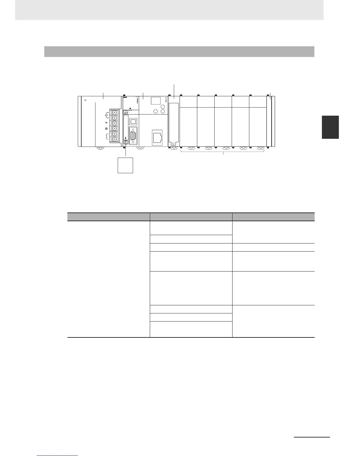
2-1-2 CPU Rack
The CPU Rack consists of a CJ2 CPU Unit, a CJ-series Power Supply Unit, CJ-series Configuration
Units, and a CJ-series End Cover. Up to 10 Configuration Units can be connected.
*1 The I/O Control Unit is required only to connect an Expansion Rack. It must be connected next to the CPU
Unit.
Although the CJ-series PLCs do not require Backplanes, the term “slot” is still used to refer to the rela-
tive position of a Unit in the Rack. Slot numbers increase toward the right side of the Rack.
2-1-2 CPU Rack
Name Configuration Remarks
CJ-series CPU Rack CJ2 CPU Unit
(One End Cover is included.)
One required for every CPU Rack.
CJ-series Power Supply Unit
Memory Card Install as required.
I/O Control Unit Required to connect an Expansion
Rack. Must be connected immedi-
ately to the right of the CPU Unit.
End Cover Must be connected to the right end
of the CPU Rack. One End Cover is
provided with the CPU Unit.
A fatal error will occur if the End
Cover is not connected.
CJ-series Basic I/O Units A total of up to 10 Units can be con-
nected to the CPU Rack and to
each of the Expansion Racks. (An
error will occur if 11 or more Units
are connected.)
CJ-series Special I/O Units
CJ-series CPU Bus Units
Memory Card
Configuration Units (10 max.)
(Basic I/O Units, Special I/O Units, CPU Bus Units)
POWER
PA205R
DC24V
AC240V
OUTPUT
RUN
INPUT
AC100-240V
L2/N
L1
CONTROLLER
PROGRAMMABLE
ERR/ALM
RUN
COMM
BKUP
INH
PRPHL
OPEN
PERIPHERAL
BUSY
MCPWR
PORT
CJ2H
CPU64-EIP
SYSMAC
NS
MS
100M
10M
COMM
CPU Unit
Power Supply Unit
End Cover
I/O Control Unit
*1