2 Basic System Configuration and Devices
2-8
CJ2 CPU Unit Hardware User’s Manual
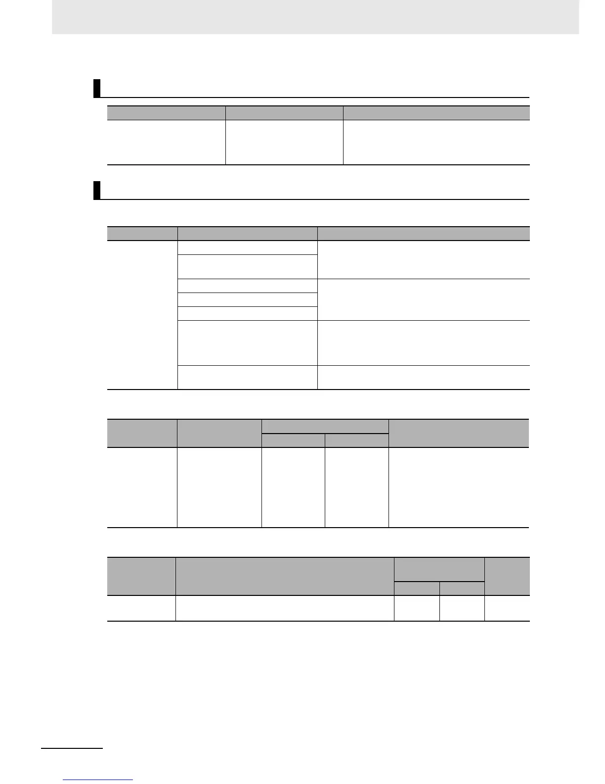
z Units for CJ-series Expansion Racks
z CJ-series Power Supply Unit
z I/O Interface Unit
*1 Includes the weight of the End Cover.
Maximum Number of Expansion Racks
Expansion pattern Maximum number of Racks Remarks
CJ-series CPU Rack plus
CJ-series Expansion Racks
3 Racks The total length of I/O Connecting Cable
between the CPU Rack and an Expansion Rack,
and between all Expansion Racks, must be no
more than 12 m.
Units
Rack Configuration Remarks
CJ-series
Expansion
Racks
CJ-series Power Supply Unit One required for each Expansion Rack. (An I/O Control
Unit is required on the CJ-series CPU Rack.)
I/O Interface Unit (one End Cover
included.)
CJ-series Basic I/O Units A total of up to 10 Units can be connected to the CPU
Rack and to each of the Expansion Racks. (An error will
occur if 11 or more Units are connected.)
CJ-series Special I/O Units
CJ-series CPU Bus Units
End Cover Must be connected to the right end of the Expansion
Rack. (One End Cover is provided with the I/O Interface
Unit. A fatal error will occur if the End Cover is not con-
nected.)
CS/CJ-series I/O Connecting Cable Required to connect the I/O Interface Unit to the I/O
Control Unit or previous I/O Interface Unit.
Model
Power supply
voltage
Output capacity
Functions
5 VDC 24 VDC
CJ1W-PA205R 100 to 240 VAC 5.0 A 0.8 A RUN output
Replacement notification
CJ1W-PA205C 100 to 240 VAC 4.6 A 0.8 A
CJ1W-PA202 100 to 240 VAC 2.8 A 0.4 A
CJ1W-PD025 24 VDC 5.0 A 0.8 A
CJ1W-PD022 24 VDC
(non-insulated type)
2.0 A 0.4 A
Model Specifications
Current consump-
tion (A)
Weight
5 VDC 24 VDC
CJ1W-II101 One Interface Unit is required for each CJ-series Expan-
sion Rack. One End Cover is provided with each Unit.
0.13 A --- 130 g
max.
*1