3 Specifications
3 - 10
OMNUC G5-series (Pulse-train Input Type) AC Servomotors and Servo Drives User’s Manual
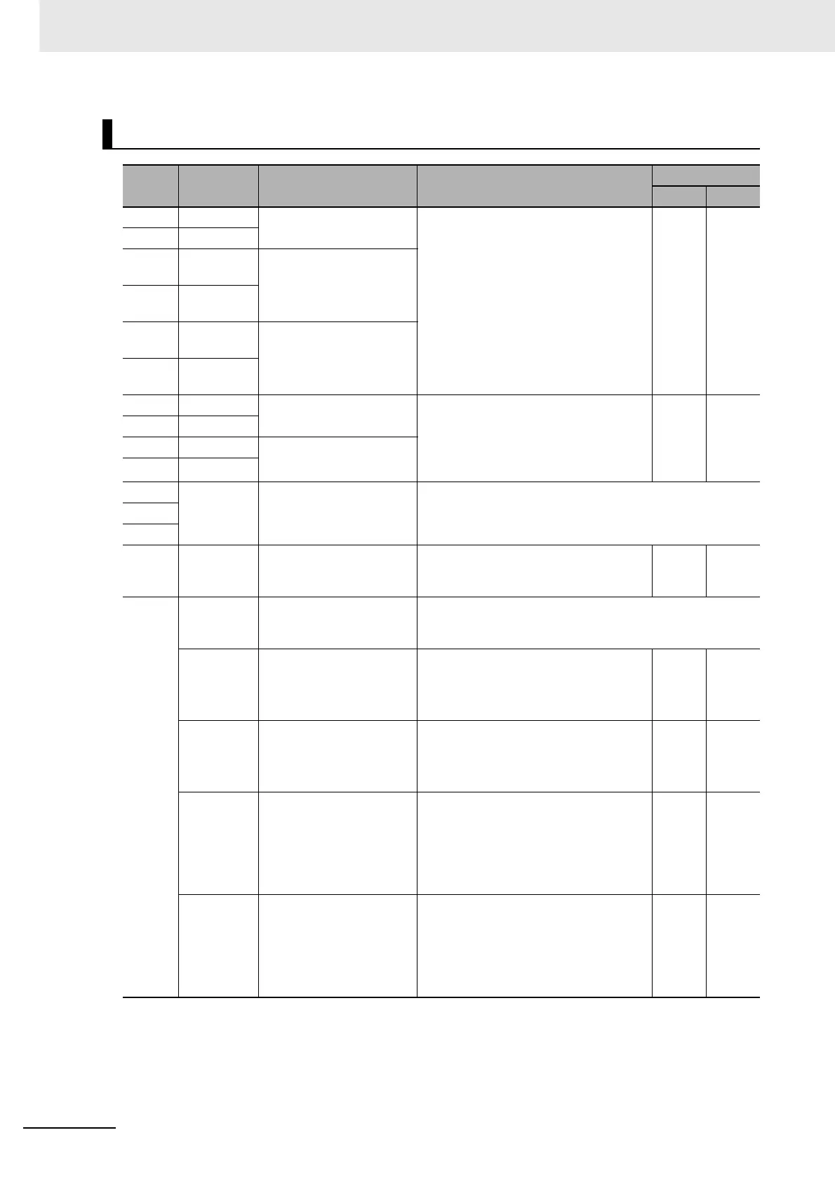
Control Inputs (CN1)
Pin No.
Symbol Name Function and interface
Control mode
Position
Speed
1 +24 VCW 24-V Open-Collector Input
for Command Pulse
These are position command pulse
input terminals for both line driver and
open collector connections.
They are enabled when Command
Pulse Input Selection (Pn005) is set to 0
(default setting).
√
2+24 VCCW
3+CW/
+PULS/+FA
Reverse Pulse,
Feed Pulse,
or 90° Phase Difference
Signal (phase A)
4–CW/
–PULS/–FA
5+CCW/
+SIGN/+FB
Forward Pulse,
Direction Signal,
or 90° Phase Difference
Signal (phase B)
6–CCW/
–SIGN/–FB
44 +CWLD Reverse Pulse
(Input for line driver only)
These are dedicated position command
pulse input terminals for the line driver
output.
They are enabled when Command Pulse
Input Selection (Pn005) is set to 1.
√
45 –CWLD
46 +CCWLD Forward Pulse
(Input for line driver only)
47 –CCWLD
13 SGGND Signal Ground This is the signal ground.
15
17
7 +24VIN 12 to 24-VDC Power
Supply Input
The forward input terminal for an
external power supply (12 to 24 VDC)
for sequence input.
√√
8,
9,
26
to
33
SI1 to SI10 Sequence Input Signal These signals are allocated with the following functions and
logics based on the values set in Input Signal Selection 1 to
10 (Pn400 to Pn409).
NOT
[8]
Reverse Drive Prohibition
Input
This signal is for reverse drive
prohibition input.
It is enabled when Drive Prohibition
Input Selection (Pn504) is set to 0 or 2.
√√
POT
[9]
Forward Drive Prohibition
Input
This signal is for forward drive
prohibition input.
It is enabled when Drive Prohibition
Input Selection (Pn504) is set to 0 or 2.
√√
DFSEL1
[26]
Damping Filter Switching 1
This signal is enabled when Damping
Filter Selection (Pn213) is set to 1 or 2.
When Damping Filter Selection (Pn213)
is set to 2, you can switch among four
filter settings in conjunction with the
Damping Filter Switching 2 (DFSEL2).
√
GSEL
[27]
Gain Switching This signal is enabled when Gain
Switching Mode (Pn115 for position
control and Pn120 for speed control) is
set to 2.
When OFF, Gain 1 is enabled. When
ON, Gain 2 is enabled.
√√

 Loading...


