3 - 11
3 Specifications
OMNUC G5-series (Pulse-train Input Type) AC Servomotors and Servo Drives User’s Manual
3-1 Servo Drive Specifications
3
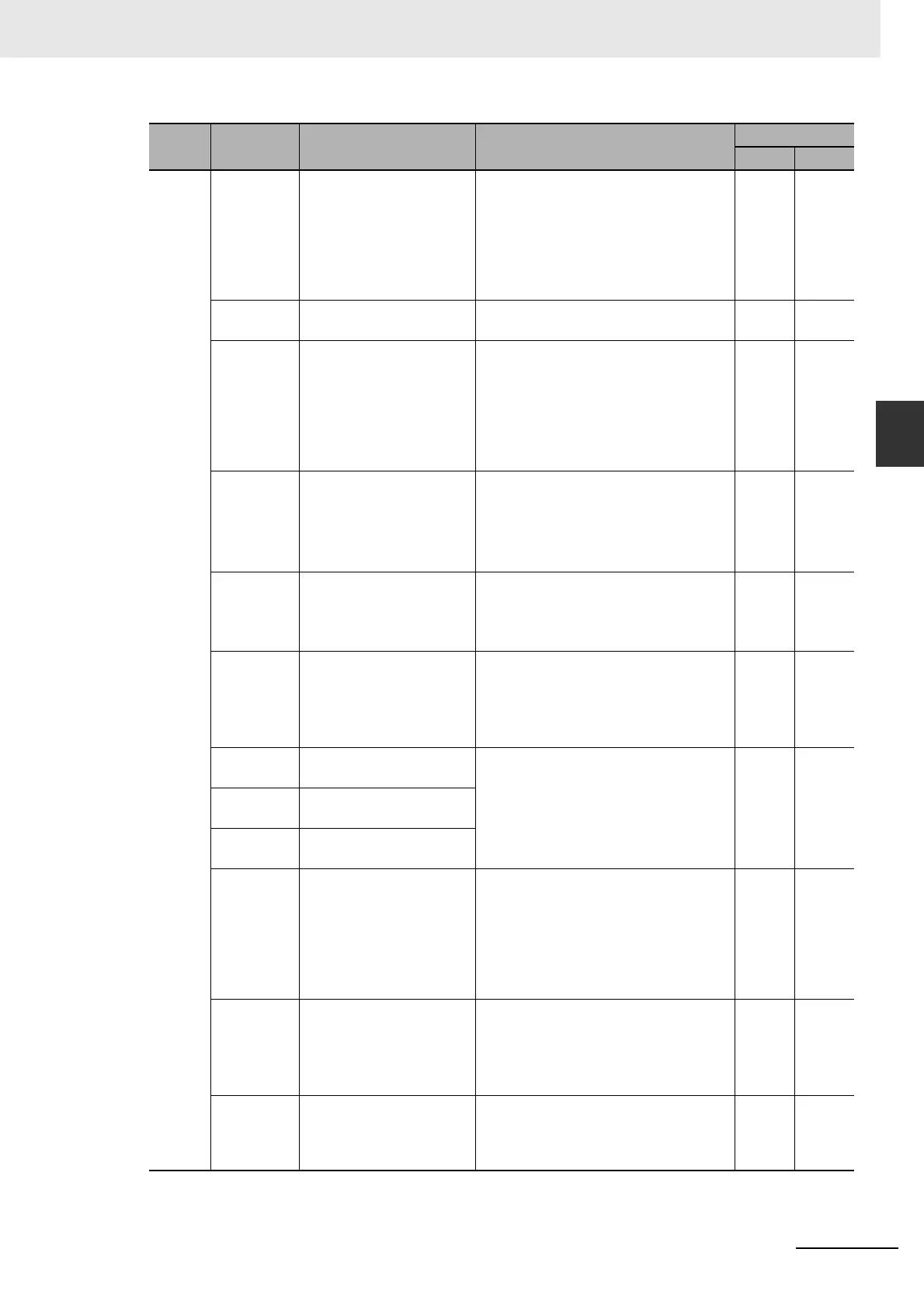
3-1-4 Control I/O Connector Specifications (CN1)
8,
9,
26
to
33
GESEL1
[28]
Electronic Gear Switching 1
This signal switches among the
Electronic Gear Ratio Numerators
settings.
You can switch among up to four
Electronic Gear Ratio Numerators
settings in conjunction with the
Electronic Gear Switching 2 (GESEL2).
√
RUN
[29]
Operation Command Input This signal turns ON the servo (to start
energizing the Servomotor).
√√
ECRST
[30]
Error Counter Reset Input This signal resets the position error
counter.
The error counter can be reset either by
the signal edge (set value: 0) or by the
signal level (set value: 1) based on the
value set in Error Counter Reset
Condition Selection (Pn517).
√
RESET
[31]
Alarm Reset Input This signal resets an alarm state.
The error counter is reset when an
alarm reset signal is input.
Some alarms cannot be reset with this
input.
√√
TVSEL
[32]
Control Mode Switching
Input
This signal switches the control mode of
the Servo Drive.
It is enabled when Control Mode
Selection (Pn001) is set to 3.
√√
IPG
[33]
Pulse Prohibition Input This signal is for position command
pulse prohibition input.
It is enabled when Command Pulse
Prohibition Input Setting (Pn518) is set
to 0.
√
VSEL1
[33]
Internally Set Speed
Selection 1
These inputs are used for selecting the
speed settings when operating the
Servomotor based on internally set
speeds (Pn304 to Pn311).
√
VSEL2
[30]
Internally Set Speed
Selection 2
VSEL3
[28]
Internally Set Speed
Selection 3
TLSEL Torque Limit Switching This signal turns ON/OFF to switch the
torque limit value.
It is enabled when Torque Limit
Selection (Pn521) is set to 3 or 6. The
torque limit value and operating
direction depend on the value set in this
parameter.
√√
DFSEL2
Damping Filter Switching 2
This signal is enabled when Damping
Filter Selection (Pn213) is set to 2.
You can switch among four filter settings
in conjunction with the Damping Filter
Switching 1 (DFSEL1).
√
GESEL2
Electronic Gear Switching 2
You can switch among up to four
Electronic Gear Ratio Numerators
settings in conjunction with the
Electronic Gear Switching 1 (GESEL1).
√
Pin No.
Symbol Name Function and interface
Control mode
Position
Speed

 Loading...


