3 Specifications
3 - 12
OMNUC G5-series (Pulse-train Input Type) AC Servomotors and Servo Drives User’s Manual
• Note that the following functions must be allocated to fixed pins.
Error Counter Reset Input (ECRST): Pin 30 only
Command Pulse Input Prohibition Input (IPG): Pin 33 only
• Each number enclosed in brackets [ ] shows the default pin number (allocation). (This allocation is
dependent on the control mode.)
8,
9,
26
to
33
VZERO Zero Speed Designation
Input
This signal forcibly sets the speed
command value to 0.
It is enabled when Zero Speed
Designation Selection (Pn315) is set to
1 to 3.
√
VSIGN Speed Command Sign
Input
This signal specifies the motor rotation
direction in the speed command.
It is enabled when Speed Command
Direction Selection (Pn301) is set to 1.
√
STOP Emergency Stop Input This signal is for emergency stop input.
When it is input, the Servo Drive
generates an Emergency Stop Input
Error and thereby stops the motor.
√√
JSEL Inertia Ratio Switching
Input
This signal switches between Inertia
Ratio 1 and Inertia Ratio 2.
√√
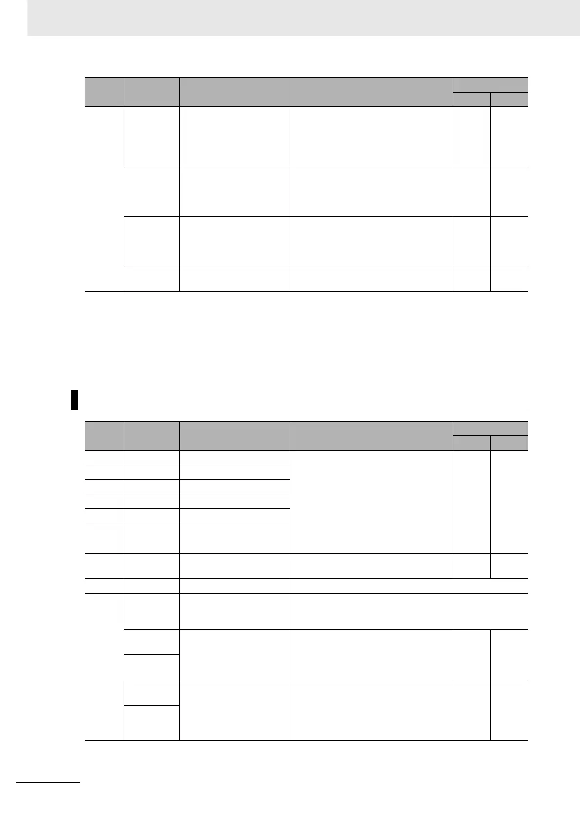
Control Outputs (CN1)
Pin No.
Symbol Name Function and interface
Control mode
Position
Speed
21 +A
Encoder Phase-A + Output
These encoder signals are output
according to the values set in Encoder
Dividing Numerator (Pn011). These are
for line driver output (equivalent to
RS422) with a maximum output
frequency of 4 Mpps.
These encoder signals are for phase-Z
output. Line driver output (equivalent to
RS422)
√
22 –A
Encoder Phase-A – Output
49 +B
Encoder Phase-B + Output
48 –B
Encoder Phase-B – Output
23 +Z
Encoder Phase-Z + Output
24 –Z
Encoder Phase-Z – Output
19 Z Encoder Phase-Z Output These encoder signals are for phase-Z
output. Open collector output
√
25 SGGND Signal Ground This is the signal ground.
10,
11,
34
to
39
SO1 to SO4 Sequence Output Signal These signals are allocated with any of the following
functions based on the values set in Output Signal
Selection 1 to 4 (Pn410 to 413).
BKIR
[11]
Brake Interlock Output This timing output signal activates the
electromagnetic brake of the
Servomotor.
√√
BKIRCOM
[10]
READY
[35]
Servo Ready Completed This output signal indicates the Servo
Drive is ready to be energized.
This signal turns ON when the control/
main power supply is ON and the Servo
Drive is not in an alarm state.
√√
READYCOM
[34]
Pin No.
Symbol Name Function and interface
Control mode
Position
Speed

 Loading...


