3 Specifications
3 - 14
OMNUC G5-series (Pulse-train Input Type) AC Servomotors and Servo Drives User’s Manual
Note Do not connect anything to unused pins (those indicated with *1).
The input functions for general-purpose inputs 1 to 10 (or SI1 to SI10) and the output functions for general-
purpose outputs (SO1, SO2 and SO4) are determined by the user parameters Pn400 to Pn409 (Input Signal
Selection 1 to 10) and Pn410 to Pn413 (Output Signal Selection 1 to 4).
The Alarm Output (/ALM) is fixed to general-purpose output 3 (those enclosed in brackets [ ] in the above
figure).
The functions that are allocated by default are given in parentheses ( ). The default function allocated to each
pin indicated with *2 is dependent on the control mode. Refer to 6-9 Sequence I/O Signals on page 6-33 for
details about function allocation.
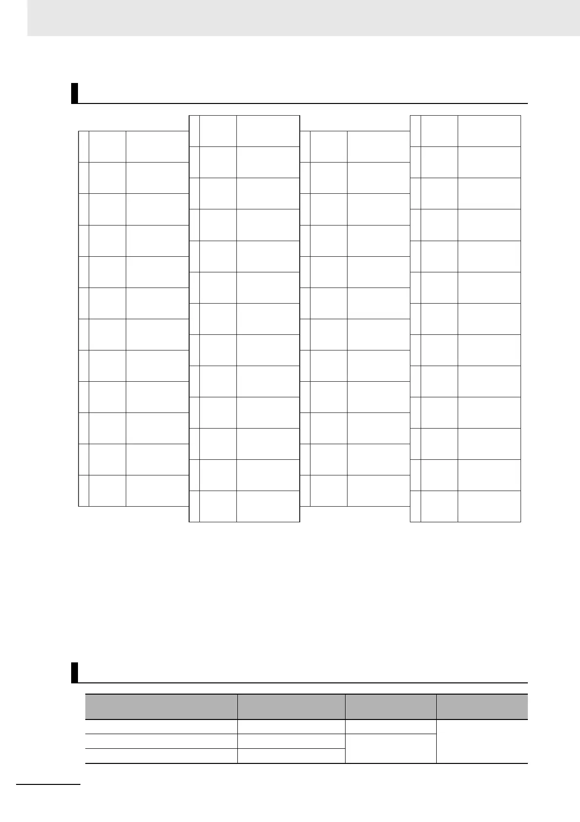
CN1 Pin Arrangement
Connectors for CN1 (50 Pins)
Name Model Manufacturer
OMRON model
number
Drive connector 52986-5079 Molex Japan R88A-CNU11C
Cable plug 10150-3000PE Sumitomo 3M
Cable case (Shell kit) 10350-52A0-008
2
4
6
8
10
12
14
16
18
20
22
24
PCOM
1
3
5
7
9
11
13
15
17
19
21
23
25
27
29
31
33
35
37
39
41
43
45
47
49
26
28
30
32
34
36
38
40
42
44
46
48
50
+CCW/
+SIGN/+FB
–CCW/
–SIGN/–FB
+CW/
+PULS/+FA
+24VIN
–CW/
–PULS/–FA
PCOM
+A
–A
–CCWLD
+CWLD
–CWLD
+CCWLD
Z
SI10
SO2COM
ALMCOM
[ SO3COM ]
/ALM
[ SO3 ]
SO4COM
SO4
SI9
(TVSEL)
–B
+B
SGGND
SI3
SI5
SI7
SO1COM
SGGND
SGGND
SGGND
+Z
–Z
SI1
(NOT)
*1
SI2
(POT)
SO1
(BKIR)
SI4
(GSEL)
SI6
(RUN)
SI8
(RESET)
*1
*1
*1
*1
*1
*1
*1
*1
*1
*2
*2
*2
*2
*2
SO2
(READY)
24-V Open-
Collector Input for
Command Pulse
Reverse Pulses,
Feed Pulses, or 90º
Phase Difference
Signal (Phase A)
Forward Pulse,
Direction Signal, or
90º Phase Difference
Signal (Phase B)
General-purpose
Input 1
(Reverse Drive
Prohibition Input)
General-purpose
Output 1 Common
Encoder
Phase-A – Output
Encoder
Phase-Z – Output
24-V Open-
Collector Input for
Command Pulse
Reverse Pulses,
Feed Pulses, or 90º
Phase Difference
Signal (Phase A)
Forward Pulse,
Direction Signal, or
90º Phase Difference
Signal (Phase B)
12 to 24-VDC
Power Supply
Input
General-purpose
Input 2
(Forward Drive
Prohibition Input)
General-purpose
Output 1
(Brake Interlock
Output)
Signal Ground
Signal Ground
Signal Ground
Phase-Z Output
(Open Collector)
Encoder
Phase-A + Output
Encoder
Phase-Z + Output
Signal Ground
General-purpose
Input 4
(Gain Switching)
General-purpose
Input 6
(Operation
Command)
General-purpose
Input 8
(Alarm Reset
Input)
General-purpose
Input 10
*2
General-purpose
Output 2
(Servo Ready
Completed Output)
Alarm Output
[General-purpose
Output 3]
General-purpose
Output 4
*2
Reverse Pulse
(Input for line
driver only)
Forward Pulse
(Input for line
driver only)
Encoder
Phase-B + Output
General-purpose
Input 3
*2
General-purpose
Input 5
*2
General-purpose
Input 7
*2
General-purpose
Input 9
(Control Mode
Switching)
General-purpose
Output 2 Common
Alarm Output
Common
[General-purpose
Output 3 Common]
General-purpose
Output 4 Common
Reverse Pulse
(Input for line
driver only)
Forward Pulse
(Input for line
driver only)
Encoder
Phase-B – Output

 Loading...


