3 Specifications
3 - 20
OMNUC G5-series (Pulse-train Input Type) AC Servomotors and Servo Drives User’s Manual
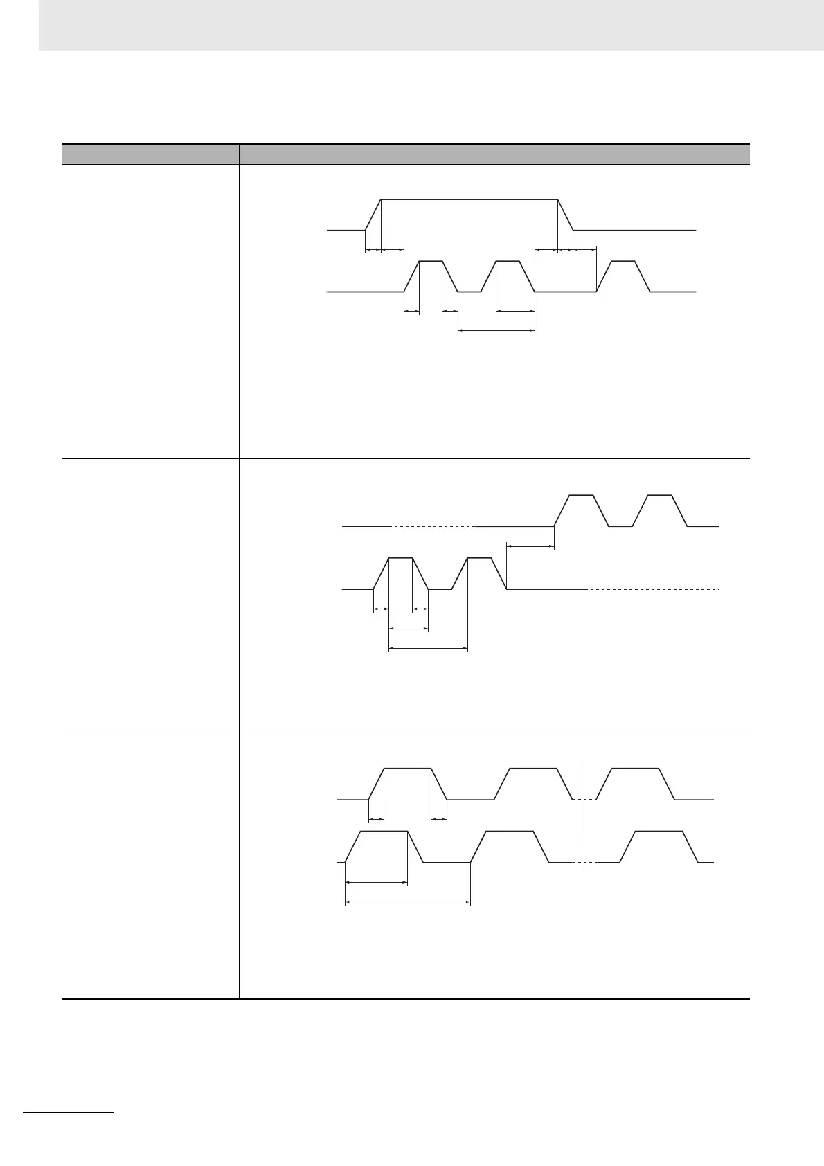
When to Input a Command Pulse (Line Receiver Input)
Command pulse mode Detailed timing
Feed Pulse/Direction Signal
Maximum input frequency
Line driver:
4 Mpps
Reverse Pulse/Forward Pulse
Maximum input frequency
Line driver:
4 Mpps
90° Phase Difference Signal
Maximum input frequency
Line driver:
4 Mpps
t1 t1t2 t2 t2
t1 t1
T
τ
t1 ≤ 20 ns
t2 > 500 ns
τ ≥ 250 ns
T ≥ 500 ns
(τ/T) x 100 ≤ 50 (%)
Direction
signal
Feed pulse
Forward rotation command Reverse rotation command
t1 ≤ 20 ns
t2 > 500 ns
τ ≥ 250 ns
T ≥ 500 ns
(τ/T) x 100 ≤ 50 (%)
T
τ
t2
t1 t1
Reverse pulse
Forward pulse
Forward rotation command
Reverse rotation command
t1 ≤ 20 ns
τ ≥ 4.0 µs
T ≥ 8.0 µs
(τ/T) x 100 ≤ 50 (%)
t1 t1
T
τ
Phase-A pulse
Phase-B pulse
Forward rotation command
Reverse rotation command

 Loading...


