3 - 19
3 Specifications
OMNUC G5-series (Pulse-train Input Type) AC Servomotors and Servo Drives User’s Manual
3-1 Servo Drive Specifications
3
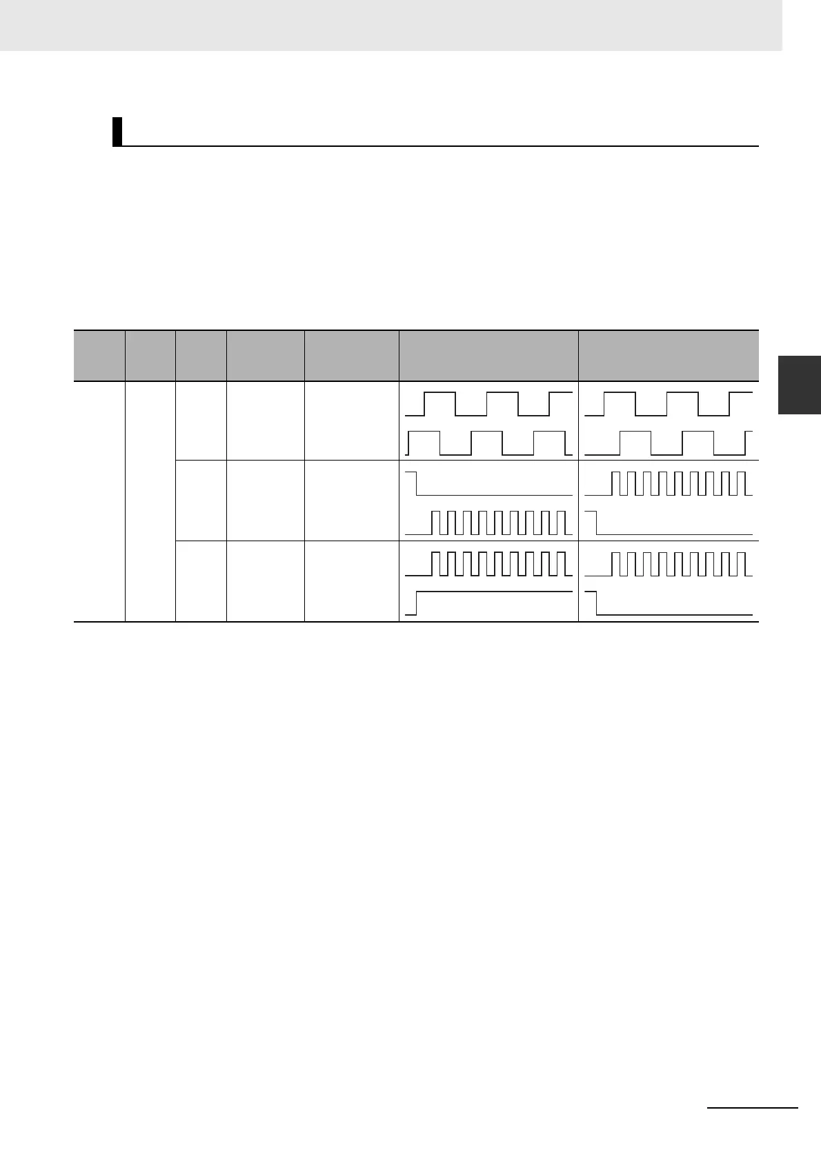
3-1-6 Control Input Details
Pin 44: + Reverse Pulse (+CW), + Feed Pulse (+PULS), + Phase A (+FA)
Pin 45: – Reverse Pulse (–CW), – Feed Pulse (–PULS), – Phase A (–FA)
Pin 46: + Forward Pulse (+CCW), + Direction Signal (+SIGN), + Phase B (+FB)
Pin 47: – Forward Pulse (–CCW), – Direction Signal (–SIGN), – Phase B (–FB)
Function
• The functions of these signals are dependent on the values set in Command Pulse Rotation
Direction Switching Selection (Pn006) and Command Pulse Mode Selection (Pn007).
Note The rotation direction is reversed when Command Pulse Rotation Direction Switching Selection (Pn006) is set to 1.
Line Receiver Input
Pn005
Set
value
Pn006
Set
value
Pn007
Set
value
Command
pulse
mode
Input pins Motor forward command Motor reverse command
1 0 0/2 90° Phase
Difference
Signal
(Quadruple)
44: +FA
45: –FA
46: +FB
47: –FB
1 Reverse
Pulse/
Forward
Pulse
44: +CW
45: –CW
46: +CCW
47: –CCW
3 Feed Pulse/
Direction
Signal
44: +PULS
45: –PULS
46: +SIGN
47: –SIGN
L
L
H
L
 Loading...


