3 - 95
3 Specifications
OMNUC G5-series (Pulse-train Input Type) AC Servomotors and Servo Drives User’s Manual
3-5 Cable and Connector Specifications
3
3-5-6 Control Cable Specifications
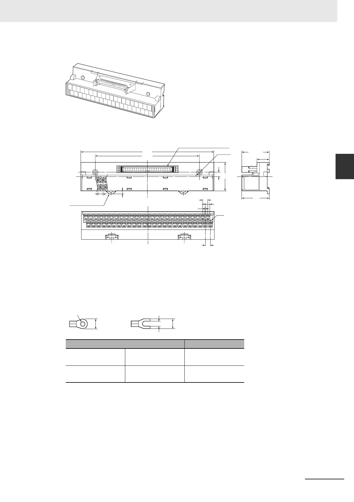
XW2D-50G6 (M3 Screw Terminal Block)
• External Dimensions
• When using crimp terminals, use crimp terminals with the following dimensions.
• When connecting wires and crimp terminals to a terminal block, tighten them to a torque of
0.7 N·m.
Applicable crimp terminals Applicable wires
Round terminals 1.25-3 AWG22 to 16
(0.3 to 1.25 mm
2
)
Fork terminals 1.25Y-3 AWG22 to 16
(0.3 to 1.25 mm
2
)
A1
A2
A3
A4
A5
A6
A7
A8
A9
A10
A11
A12
A13
A14
A15
A16
A17
A18
A20
A19
B1
B2
B3
B4 B5 B6
B7
B8
B9
B10
B11
B12
B13
B14
B15
B16
B17
B18
B19
B20
6
40
(4.5)
7
39
(39.1)
17.6
2-φ4.5
7
7
M3
5.8
1.2
184
144
MIL-type connector XG4A
DIN rail lock
Round terminal
Fork terminal
5.8 mm max.
φ3.2 mm
3.2 mm
5.8 mm max.

 Loading...


