3 - 97
3 Specifications
OMNUC G5-series (Pulse-train Input Type) AC Servomotors and Servo Drives User’s Manual
3-6 Servo Relay Unit and Cable Specifications
3
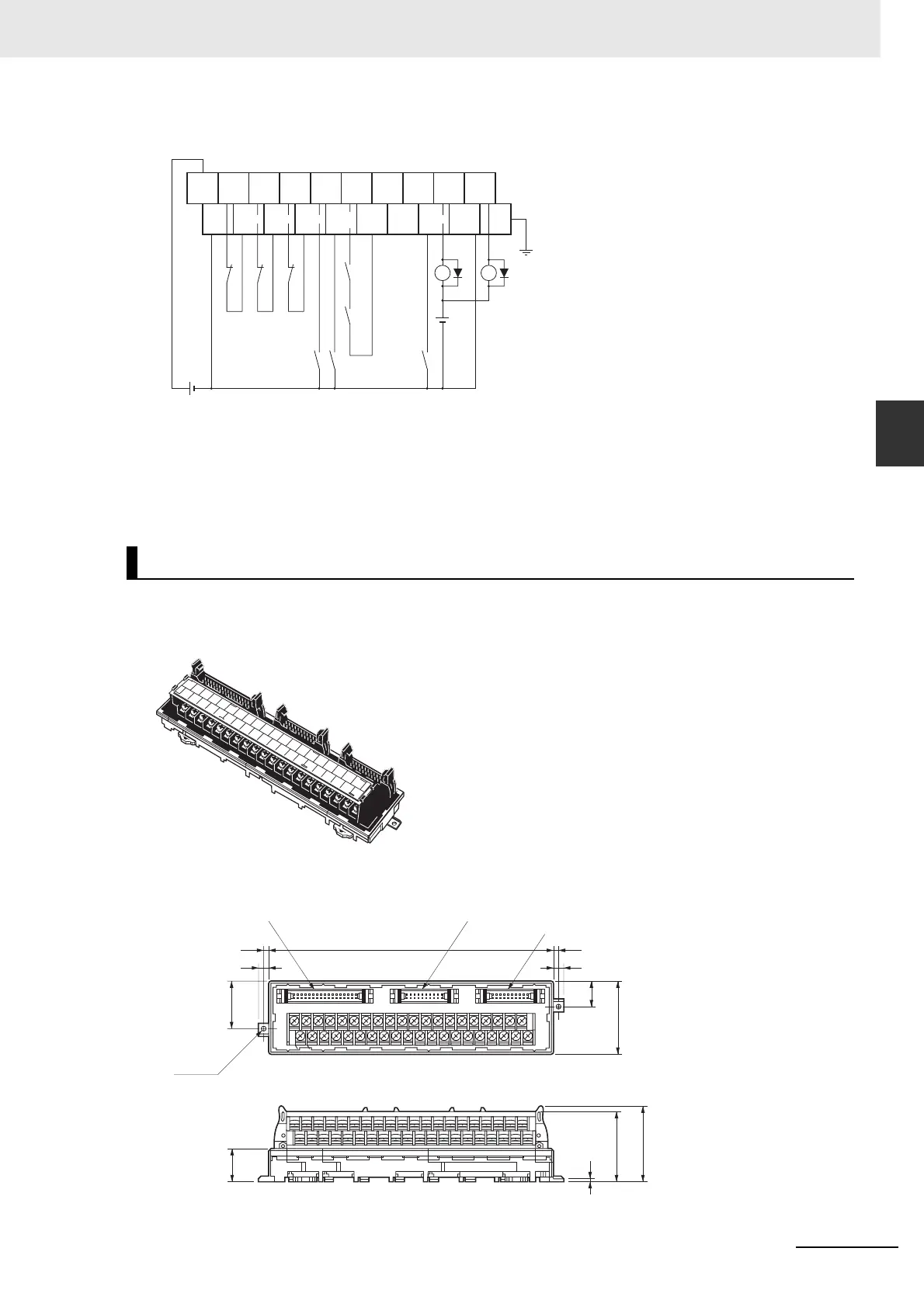
3-6-1 Servo Relay Unit Specifications
Wiring
*1 The XB contact is used to turn ON/OFF the electromagnetic brake.
Note 1 Do not connect wires to unused terminals.
2 0V and common terminals are connected internally.
3 The applicable crimp terminal is R1.25-3 (round or fork type).
Below are the specifications of the Servo Relay Unit for connecting the following OMRON Position
Control Unit models.
External Dimensions
• The pitch of terminals is 7.62 mm.
XW2B-40J6-2B
• CJ1W-NC213/-NC233/-NC413/-NC433
• CS1W-NC213/-NC233/-NC413/-NC433
• C200HW-NC213/-NC413
0V
RUN ALM BKIR10
0
19
9
RESET
ALMCOM
FG
24 VDC
Ground to
100 Ω or less
X1 XB
24 VDC
X1
(*1)
CW
limit
CCW
limit
+24V
Common Common Common CommonCommon
Emergency
stop
Origin
proximity
External
interrupt
0
1
2
3
4
5
6
7
8
9
10
11
12
13
14
15
16
17
18
19
20
21
22
23
24
25
26
27
28
29
30
31
32
33
34
35
36
37
38
39
29.5
7
3.5 180 3.5
7
45
15.5
0
20
19
39
20.5
44.3
2
Y-axis Servo Drive side
X-axis Servo Drive sidePosition Control Unit side
(46)
2-φ3.5

 Loading...


