EasyManuals Logo

Omron G5 Series User Manual

Omron G5 Series
506 pages
To Next Page IconTo Next Page
To Previous Page IconTo Previous Page
Page #207 background imageLoading...
Page #207 background image
3 - 107
3 Specifications
OMNUC G5-series (Pulse-train Input Type) AC Servomotors and Servo Drives User’s Manual
3-6 Servo Relay Unit and Cable Specifications
3
3-6-1 Servo Relay Unit Specifications
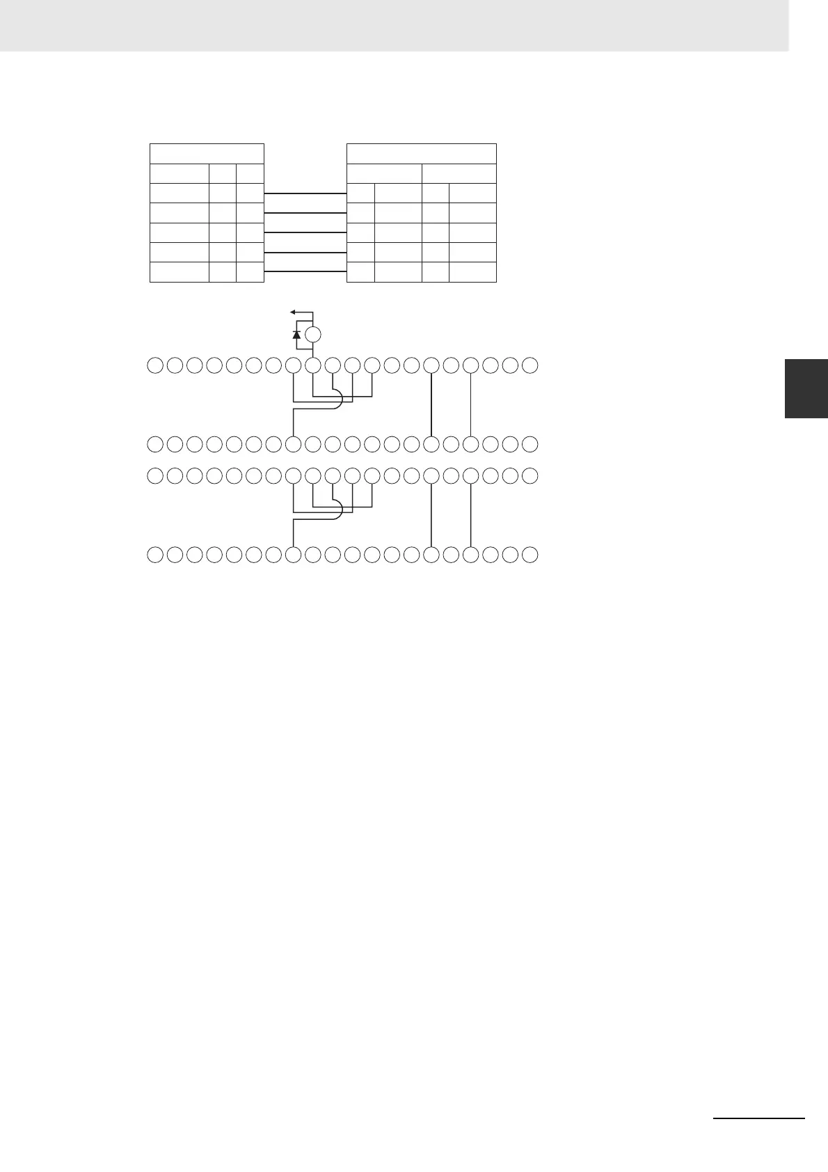
Wiring Example
Servo-side signal
RUN
ECRST
INP
/ALM
#1 #2
74
76
47
67
34
36
7
27
FQM1-side signal
For Servo #1 For Servo #2
54
56
69
70
14
16
29
30
OUT0
OUT2
OUT4
OUT6
BKIR 68 28 71 31
IN6 IN10
IN4
IN5
IN8
IN9
60 61 62 63 64 65 66 67 69 70 71 72 73 74 75 76 77 78 79
40 41 42 43 44 45 46 47 48 49 50 51 52 53 54 55 56 57 58 59
20 21 22 23 24 25 26 27 28 29 30 31 32 33 34 35 36 37 38 39
0 1 2 3 4 5 6 7 8 9 10 11 12 13 14 15 16 17 18 19
68
XB
Terminal block No.20
+24 V

Table of Contents

Other manuals for Omron G5 Series

Questions and Answers:

Question and Answer IconNeed help?

Do you have a question about the Omron G5 Series and is the answer not in the manual?

Omron G5 Series Specifications

General IconGeneral
FeedbackIncremental Encoder, Absolute Encoder
CommunicationEtherCAT
Safety FunctionSTO (Safe Torque Off)
Protection FunctionsOvervoltage, Undervoltage, Overcurrent
Vibration Resistance4.9 m/s² (10 to 55 Hz)

Related product manuals