4 System Design
4 - 4
OMNUC G5-series (Pulse-train Input Type) AC Servomotors and Servo Drives User’s Manual
• For the allowable axial loads for motors, refer to
3-1-2 Characteristics on page 3-3. If an axial load
greater than that specified is applied to a motor, it
may reduce the limit of the motor bearings and
may break the motor shaft.
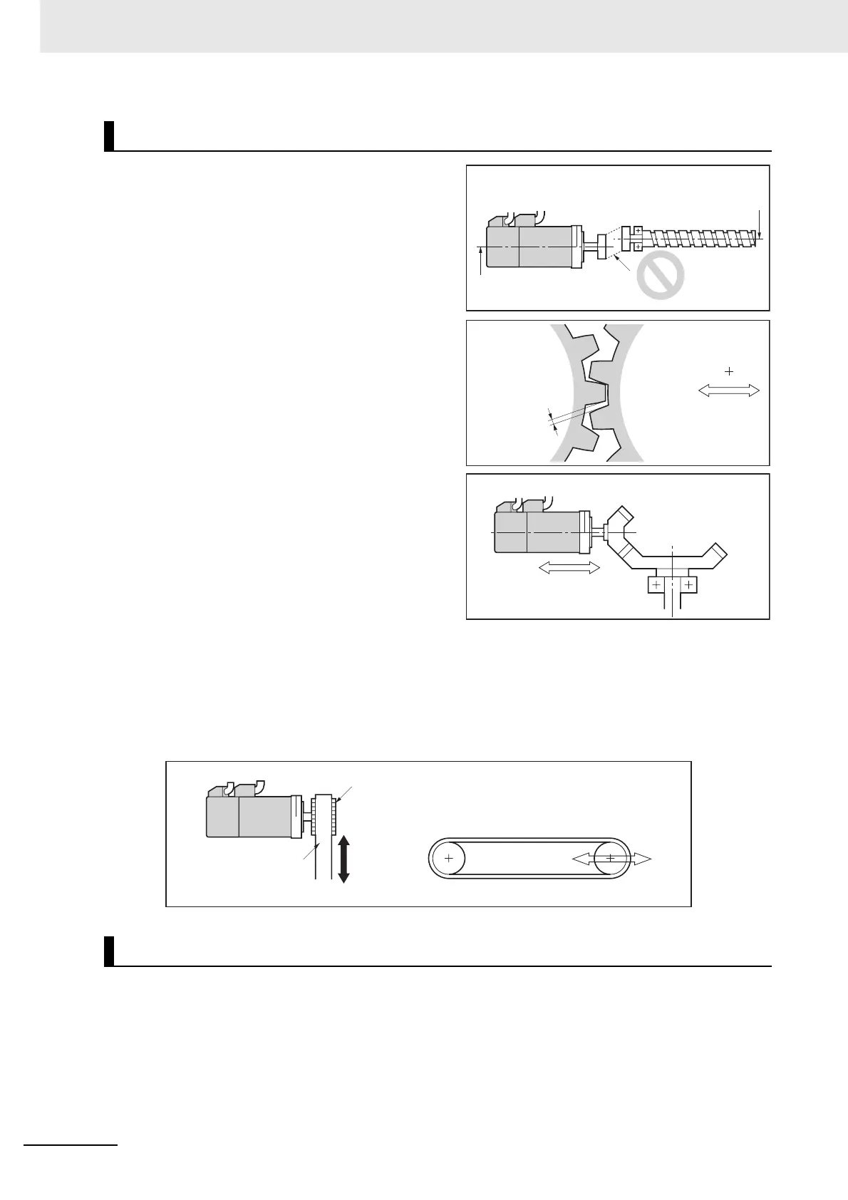
• When connecting to a load, use couplings that can
sufficiently absorb mechanical eccentricity and
declination.
• For spur gears, an extremely large radial load may
be applied depending on the gear precision. Use
spur gears with a high degree of precision (for
example, JIS class 2: normal line pitch error of
6 µm max. for a pitch circle diameter of 50 mm).
• If the gear precision is not adequate, allow
backlash to ensure that no radial load is placed on
the motor shaft.
• When using bevel gears, a load is applied in the
thrust direction depending on the structural
precision, the gear precision, and temperature
changes. Provide appropriate backlash or take
other measures to ensure that a thrust load larger
than the specified level is not applied.
• Do not put rubber packing on the flange surface. If
the flange is mounted with rubber packing, the
motor flange may crack under the tightening force.
• When connecting to a V-belt or timing belt, consult
the manufacturer for belt selection and tension.
• A radial load twice as large as the belt tension will be placed on the motor shaft. Do not allow a load
that exceeds the allowable radial load to be placed on the motor shaft. If an excessive radial load is
applied, the motor shaft and bearings may be damaged.
• Set up a movable pulley in the middle of the motor shaft and the load shaft so that the belt tension
can be adjusted.
• The protective structure for the motors is as follows:
Equivalent to IP65 (except for through-shaft parts)
Connecting to Mechanical Systems
Water and Drip Resistance
Set a movable
structure.
Bevel gear
Set a structure in
which the distance
between axes can
be adjusted.
Backlash
Motor center line
Ball screw center line
Axial offset
Axial offset
Pulley
Belt
Tension
Tension adjustment
(Set a movable structure.)

 Loading...


