4 - 9
4 System Design
OMNUC G5-series (Pulse-train Input Type) AC Servomotors and Servo Drives User’s Manual
4-1 Installation Conditions
4
4-1-3 Decelerator Installation Conditions
Installing Decelerator
When installing the R88G-VRSF, first make sure that the mounting surface is flat and that
there are no burrs on the tap sections, and then fix the mounting flanges with bolts.
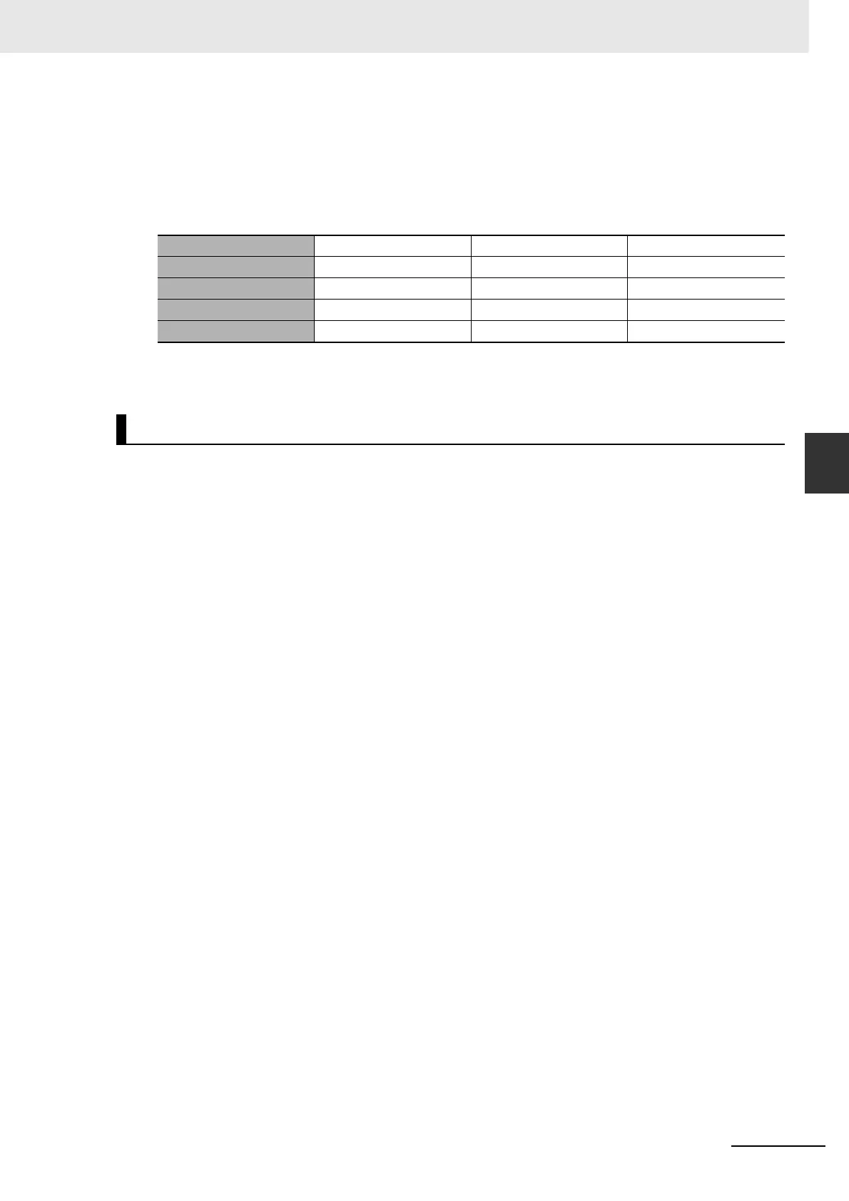
Bolt tightening torque on the mounting flange (for aluminum)
Note Uninstalling the key on a Servomotor with key enables you to install the Servomotor to the decelerator.
Slipping does not occur.
If the system configuration requires a non-OMRON decelerator to be used in combination with an
OMNUC G5-series (Pulse-train Input Type) Servomotor, select the decelerator so that the loads on the
motor shaft (i.e., both the radial and thrust loads) are within the allowable ranges. (Refer to 3-1-2
Characteristics on page 3-3 for details on the allowable loads for the motors.)
Also, select the decelerator so that the allowable input rotation speed and allowable input torque of the
decelerator are not exceeded.
R88G-VRSF Frame B Frame C Frame D
Number of bolts 444
Size of bolts M5 M6 M8
Mounting PCD [mm] 60 90 115
Tightening torque [N·m] 5.8 9.8 19.6
Using a Non-OMRON Decelerator (Reference)

 Loading...


