4 - 29
4 System Design
OMNUC G5-series (Pulse-train Input Type) AC Servomotors and Servo Drives User’s Manual
4-3 Wiring Conforming to EMC Directives
4
4-3-2 Selecting Connection Components
Use one of the following filters to prevent switching noise of PWM of the Servo Drive and to prevent
noise emitted from the internal clock circuit.
*1 Generally used for 1.5 kW or higher.
*2 Generally used for 1.5 kW or lower. The maximum number of windings is 3 turns.
*3 Generally used for 50/100 W. The maximum number of windings is 2 turns.
*4 Also used on the Drive output power lines to comply with the EMC Directives. Only a clamp is used. This clamp
can also be used to reduce noise current on a FG line.
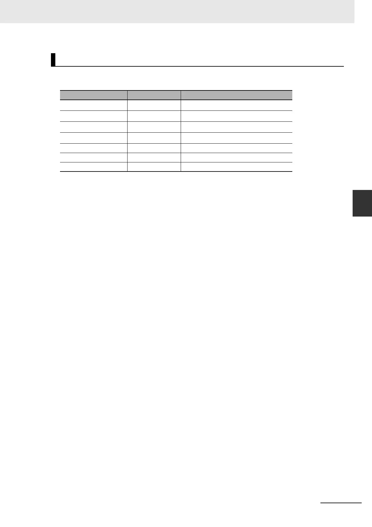
Radio Noise Filter and Emission Noise Prevention Clamp Core
Model Manufacturer Application
3G3AX-ZCL1
*1
OMRON For Drive output and power cable
3G3AX-ZCL2
*2
OMRON For Drive output and power cable
ESD-R-47B
*3
NEC TOKIN For Drive output and power cable
ZCAT3035-1330
*4
TDK For Encoder cable and I/O cable
RJ8035 Konno Industry For power supply line
RJ8095 Konno Industry For power supply line
T400-61D MICROMETALS For Drive output and power cable

 Loading...


