6 - 35
6 Applied Functions
OMNUC G5-series (Pulse-train Input Type) AC Servomotors and Servo Drives User’s Manual
6-9 Sequence I/O Signals
6
6-9-2 Input Signals
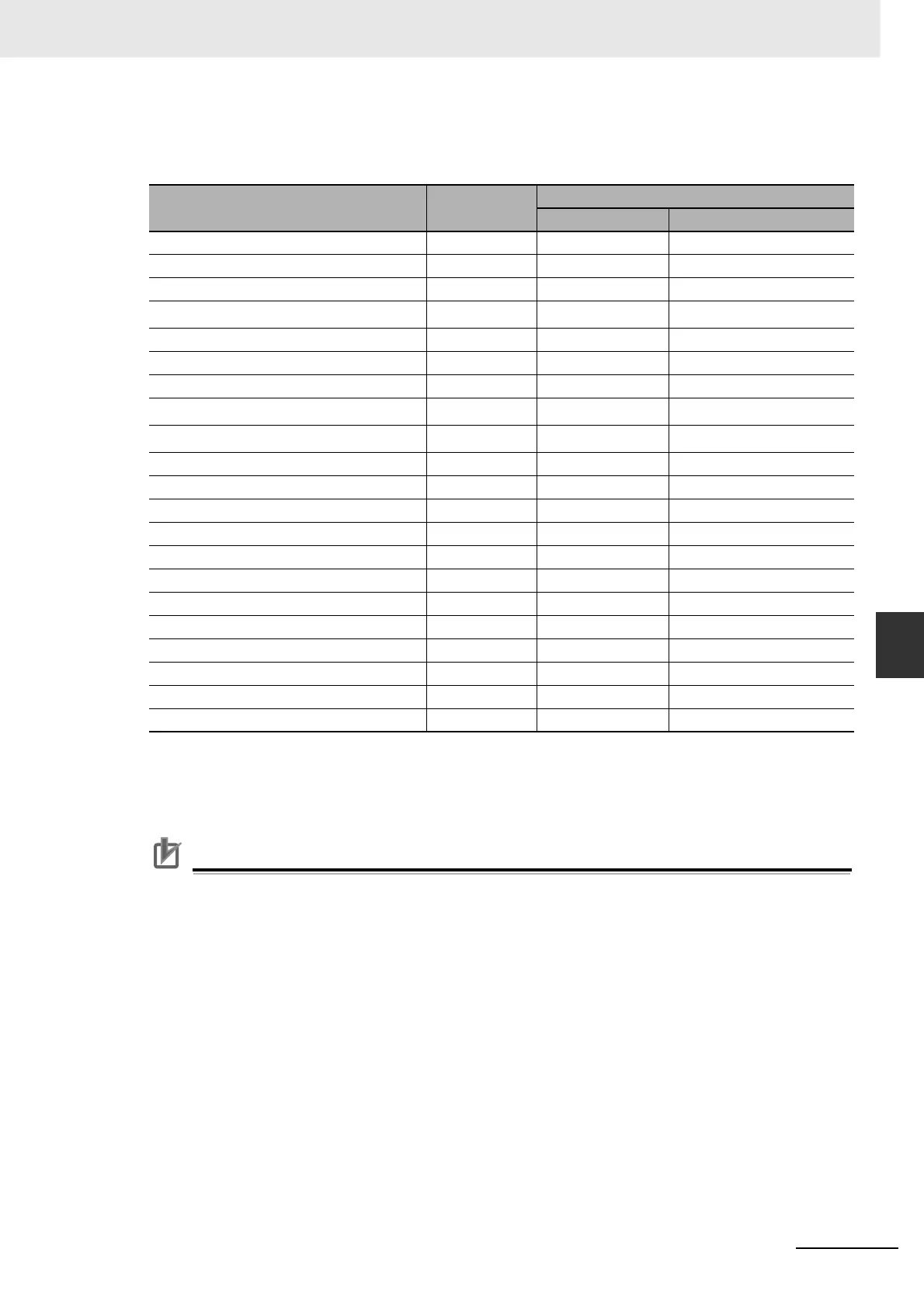
Function Number Table
The set values to be used for allocations are as follows:
*1 The Operation Command (RUN) must be allocated. Servo cannot be turned ON if it is not allocated.
*2 Allocate this signal to Input Signal Selection 7 (Pn406). If it is allocated to any other signal, an alarm will occur.
*3 Allocate this signal to Input Signal Selection 10 (Pn409). If it is allocated to any other signal, an alarm will
occur.
Precautions for Correct UsePrecautions for Correct Use
• Do not use any values other than the settings listed.
• If you allocate the same function to more than one input signal, Interface Input Duplicate
Allocation Error 1 (Alarm No. 33.0) or Interface Input Duplicate Allocation Error 2 (Alarm No.
33.1) will occur.
• Error Counter Reset Input (ECRST) can be allocated only to Input Signal Selection 7 (Pn406).
If it is allocated to other signals, Counter Reset Allocation Error (Alarm No. 33.6) will occur.
• Pulse Prohibition Input (IPG) can be allocated only to Input Signal Selection 10 (Pn409). If it is
allocated to signals, Command Pulse Prohibition Input Allocation Error (Alarm No. 33.7) will
occur.
• To use Control Mode Switching Input (TVSEL), it must be set for all control modes. Otherwise,
Interface Input Function Number Error 1 (Alarm No. 33.2) or Interface Input Function Number
Error 2 (Alarm No. 33.3) will occur.
• If Zero Speed Designation Selection (Pn315) is set to 2 or 3, the Zero Speed Designation
Input (VZERO) for the position control must be allocated to the same pin as that to which the
Zero Speed Designation Input (VZERO) for the speed control is allocated. The logic must also
be allocated in the same method.
Signal Symbol
Set value
NO NC
Disabled – 00 hex Setting not available
Forward Drive Prohibition Input POT 01 hex 81 hex
Reverse Drive Prohibition Input NOT 02 hex 82 hex
Operation Command
*1
RUN 03 hex 83 hex
Alarm Reset Input RESET 04 hex Setting not available
Control Mode Switching Input TVSEL 05 hex 85 hex
Gain Switching GSEL 06 hex 86 hex
Error Counter Reset Input
*2
ECRST 07 hex Setting not available
Pulse Prohibition Input
*3
IPG 08 hex 88 hex
Torque Limit Switching TLSEL 09 hex 89 hex
Damping Filter Switching 1 DFSEL1 0A hex 8A hex
Damping Filter Switching 2 DFSEL2 0B hex 8B hex
Electronic Gear Switching Input 1 GESEL1 0C hex 8C hex
Electronic Gear Switching Input 2 GESEL2 0D hex 8D hex
No. 1 Internally Set Speed VSEL1 0E hex 8E hex
No. 2 Internally Set Speed VSEL2 0F hex 8F hex
No. 3 Internally Set Speed VSEL3 10 hex 90 hex
Zero Speed Designation Input VZERO 11 hex 91 hex
Speed Command Sign Input VSIGN 12 hex 92 hex
Emergency Stop Input STOP 14 hex 94 hex
Inertia Ratio Switching Input J-SEL 15 hex 95 hex

 Loading...


