7 - 17
7 Parameter Details
OMNUC G5-series (Pulse-train Input Type) AC Servomotors and Servo Drives User’s Manual
7-2 Gain Parameters
7
Explanation of Settings
(√: Enabled, –: Disabled)
• Select the conditions for switching between Gain 1 and Gain 2 when Gain Switching Input Operating
Mode Selection (Pn114) is set to 1.
• This setting is fixed to Gain 1 regardless of the gain input, when Switching Mode in Speed Control
(Pn120) is set to 1 and Torque Limit Selection (Pn521) is set to 3 or 6.
*1 Gain Switching Delay Time in Speed Control (Pn121) becomes effective when the gain is switched from 2 to 1.
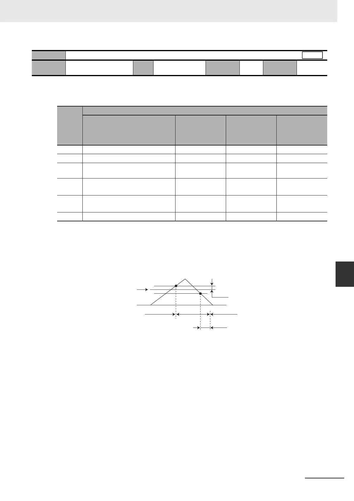
*2 The definition of Gain Switching Hysteresis in Speed Control (Pn123) is shown in the drawing below.
*3 This represents the amount of change during the period of 1 ms.
Example: To switch the gain if the torque variation during 1 ms is 10%, set these parameters to 200.
*4 When the set value is 10, the meanings of Gain Switching Delay Time in Speed Control (Pn121), Gain
Switching Level in Speed Control (Pn122), and Gain Switching Hysteresis in Speed Control (Pn123) differ from
the normal case. (Refer to Figure D.)
Pn120
Switching Mode in Speed Control
Setting
range
0 to 5 Unit – Default
setting
0
Cycle the
power supply
–
Set
value
Description
Gain switching conditions
Gain Switching
Delay Time in
Speed Control
(Pn121)
*1
Gain Switching
Level in Speed
Control (Pn122)
Gain Switching
Hysteresis in
Speed Control
(Pn123)
*2
0 Always Gain 1 (Pn100 to Pn104). – – –
1 Always Gain 2 (Pn105 to Pn109). – – –
2 Switching using gain switching input
(GSEL) (CN1 pin 27)
–––
3 Amount of change in torque
command (Refer to Figure A.)
√
√
*3
(0.05%)
√
*3
(0.05%)
4 Amount of change in speed
command (Refer to Figure B.)
√
√
*4
[10 r/min/s]
√
*4
[10 r/min/s]
5 Speed command (Refer to Figure C.) √√ [r/min] √ [r/min]
Speed
Pn122
0
Pn123
Pn121
Gain 1
Gain 2
Gain 1

 Loading...


