7 Parameter Details
7 - 18
OMNUC G5-series (Pulse-train Input Type) AC Servomotors and Servo Drives User’s Manual
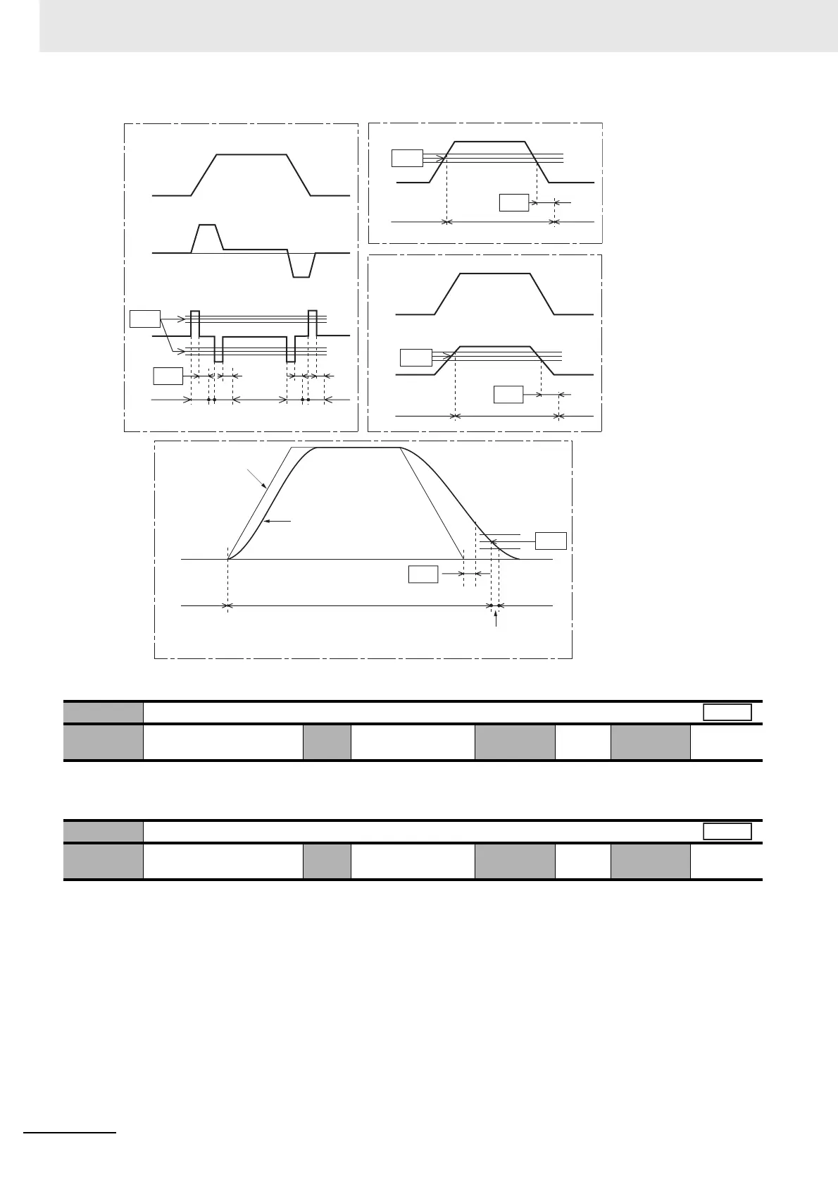
• Set the delay time when returning from Gain 2 to Gain 1 if Switching Mode in Speed Control (Pn120)
is set to 3 to 5.
• This parameter is enabled in the speed control mode when Switching Mode in Speed Control
(Pn120) is 3 to 5. It sets the judgment level for switching between Gain 1 and Gain 2. The unit
depends on the setting of Switching Mode in Speed Control (Pn120).
Pn121
Gain Switching Delay Time in Speed Control
Setting
range
0 to 10,000 Unit 0.1 ms Default
setting
0
Cycle the
power supply
–
Pn122
Gain Switching Level in Speed Control
Setting
range
0 to 20,000 Unit – Default
setting
0
Cycle the
power supply
–
H
L
H
L
H
L
H
L
Figure A
Speed V
Torque T
T
Time
1
1
22 22
1
1Gain 1
Figure C
Speed V
Gain 1 Gain 1Gain 2
Accumulated pulse
Level
Time
Figure B
Speed V
Gain 1 Gain 1Gain 2
Time
Command speed S
Gain 1 Gain 2
Actual speed N
Time
H
L
Gain 1
Gain 2 for speed loop integral time constant only;
Gain 1 for others
Figure D
Level
Level
Level
Speed
Speed

 Loading...


