7 - 19
7 Parameter Details
OMNUC G5-series (Pulse-train Input Type) AC Servomotors and Servo Drives User’s Manual
7-2 Gain Parameters
7
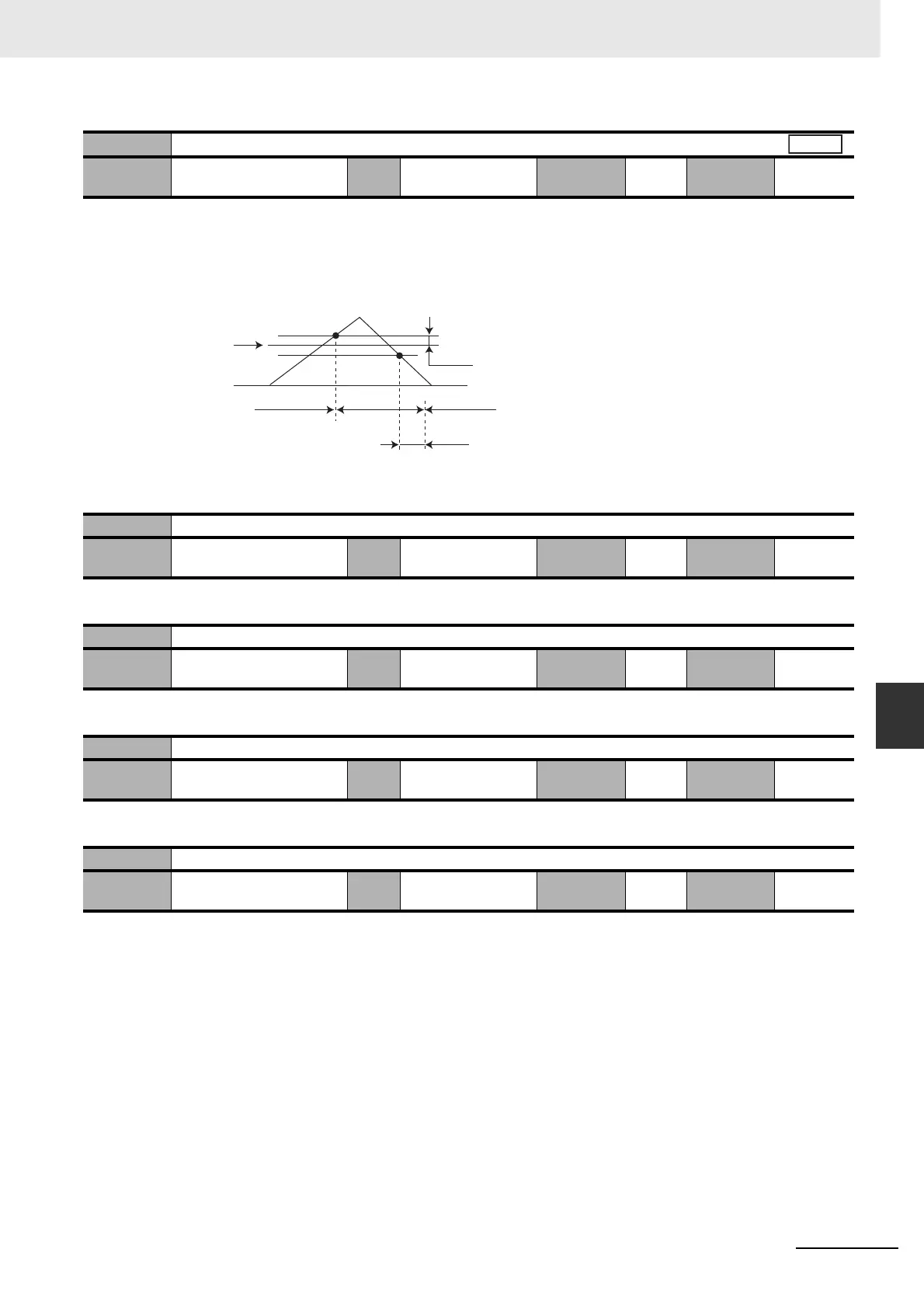
• Set the hysteresis width above and below the judgment level set in Gain Switching Level in Speed
Control (Pn122). The unit depends on the setting of Switching Mode in Speed Control (Pn120).
The definitions of Gain Switching Delay Time in Speed Control (Pn121), Gain Switching Level in
Speed Control (Pn122), and Gain Switching Hysteresis in Speed Control (Pn123) are shown in the
drawing below.
• The settings for Gain Switching Level in Speed Control (Pn122) and Gain Switching Hysteresis in
Speed Control (Pn123) are enabled as absolute values (forward/reverse).
• Do not set.
• Do not set.
• Do not set.
• Do not set.
Pn123
Gain Switching Hysteresis in Speed Control
Setting
range
0 to 20,000 Unit – Default
setting
0
Cycle the
power supply
–
Pn124 Reserved
Setting
range
0 Unit – Default
setting
0
Cycle the
power supply
–
Pn125 Reserved
Setting
range
0 Unit – Default
setting
0
Cycle the
power supply
–
Pn126 Reserved
Setting
range
0 Unit – Default
setting
0
Cycle the
power supply
–
Pn127 Reserved
Setting
range
0 Unit – Default
setting
0
Cycle the
power supply
–
Speed
Pn122
0
Pn123
Pn121
Gain 1
Gain 2
Gain 1

 Loading...


