7 - 33
7 Parameter Details
OMNUC G5-series (Pulse-train Input Type) AC Servomotors and Servo Drives User’s Manual
7-5 Interface Monitor Setting Parameters
7
• For the setting method, refer also to 6-9 Sequence I/O Signals on page 6-33.
Explanation of Set Values
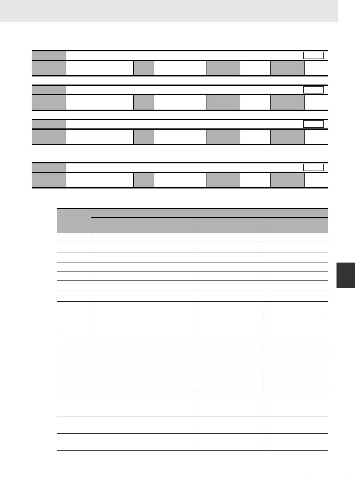
Pn411
Output Signal Selection 2
Setting
range
0 to 00FFFFFF hex Unit – Default
setting
131,586
Cycle the
power supply
Required
Pn412
Not used
Setting
range
– Unit – Default
setting
–
Cycle the
power supply
–
Pn413
Output Signal Selection 4
Setting
range
0 to 00FFFFFF hex Unit – Default
setting
328,964
Cycle the
power supply
Required
Pn416
Analog Monitor 1 Selection
Setting
range
0 to 21 Unit – Default
setting
0
Cycle the
power supply
–
Set value
Description
Monitor type Unit
Output gain when
Pn417 = 0
0 Motor speed r/min 500
1
Position command speed
*2
r/min 500
2
Internal position command speed
*2
r/min 500
3 Speed control command r/min 500
4 Torque command % (Rated torque ratio) 33
5
Position command error
*3
– 3,000
6
Encoder position error
*3
Pulses (encoder units) 3,000
7 Reserved
(Do not set.)
– 3,000
8 Reserved
(Do not set.)
– 3,000
9 P-N voltage V 80
10 Regeneration load ratio % 33
11 Overload load ratio % 33
12 Forward direction torque limit % (Rated torque ratio) 33
13 Reverse direction torque limit % (Rated torque ratio) 33
14 Speed limit value r/min 500
15 Inertia ratio % 500
16 Reserved
(Do not set.)
–1
17 Reserved
(Do not set.)
–1
18 Reserved
(Do not set.)
–1
All
All
All
All

 Loading...


