7 - 35
7 Parameter Details
OMNUC G5-series (Pulse-train Input Type) AC Servomotors and Servo Drives User’s Manual
7-5 Interface Monitor Setting Parameters
7
• Set the output gain of the analog monitor 2.
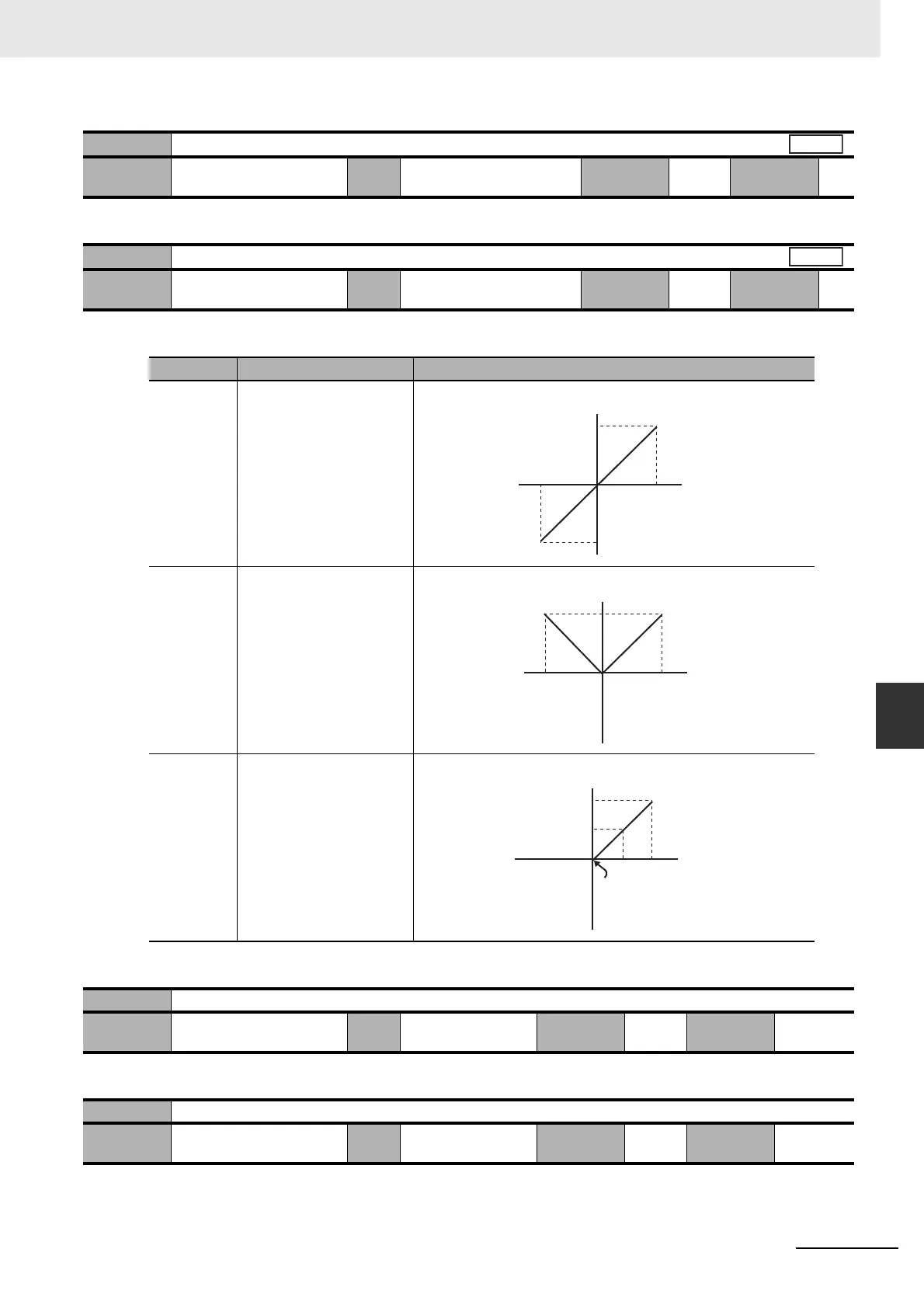
• Select the analog monitor output voltage direction.
• An example when the monitor type is Motor speed and the conversion gain is 500 (1 V = 500 r/min)
• Do not set.
• Do not set.
Pn419
Analog Monitor 2 Scale Setting
Setting
range
0 to 214,748,364 Unit Pn418 monitor unit/V Default
setting
0
Cycle the
power supply
–
Pn421
Analog Monitor Output Setting
Setting
range
0 to 2 Unit – Default
setting
0
Cycle the
power supply
–
Set value Output range Data output
0 –10 to 10 V
1 0 to 10 V
2 0 to 10 V
Pn422 Reserved
Setting
range
0 Unit – Default
setting
0
Cycle the
power supply
–
Pn423 Reserved
Setting
range
0 Unit – Default
setting
0
Cycle the
power supply
–
All
All
10 V
–10 V
0 V
–5,000 5,000 [r/min]
Motor
speed
Output voltage [V]
10 V
–10 V
0 V
–5,000 5,000 [r/min]
Motor
speed
Output voltage [V]
10 V
5 V
–10 V
0 V 0
–2,500
5,000 [r/min]
Motor
speed
Output voltage [V]

 Loading...


