9 Adjustment Functions
9 - 14
OMNUC G5-series (Pulse-train Input Type) AC Servomotors and Servo Drives User’s Manual
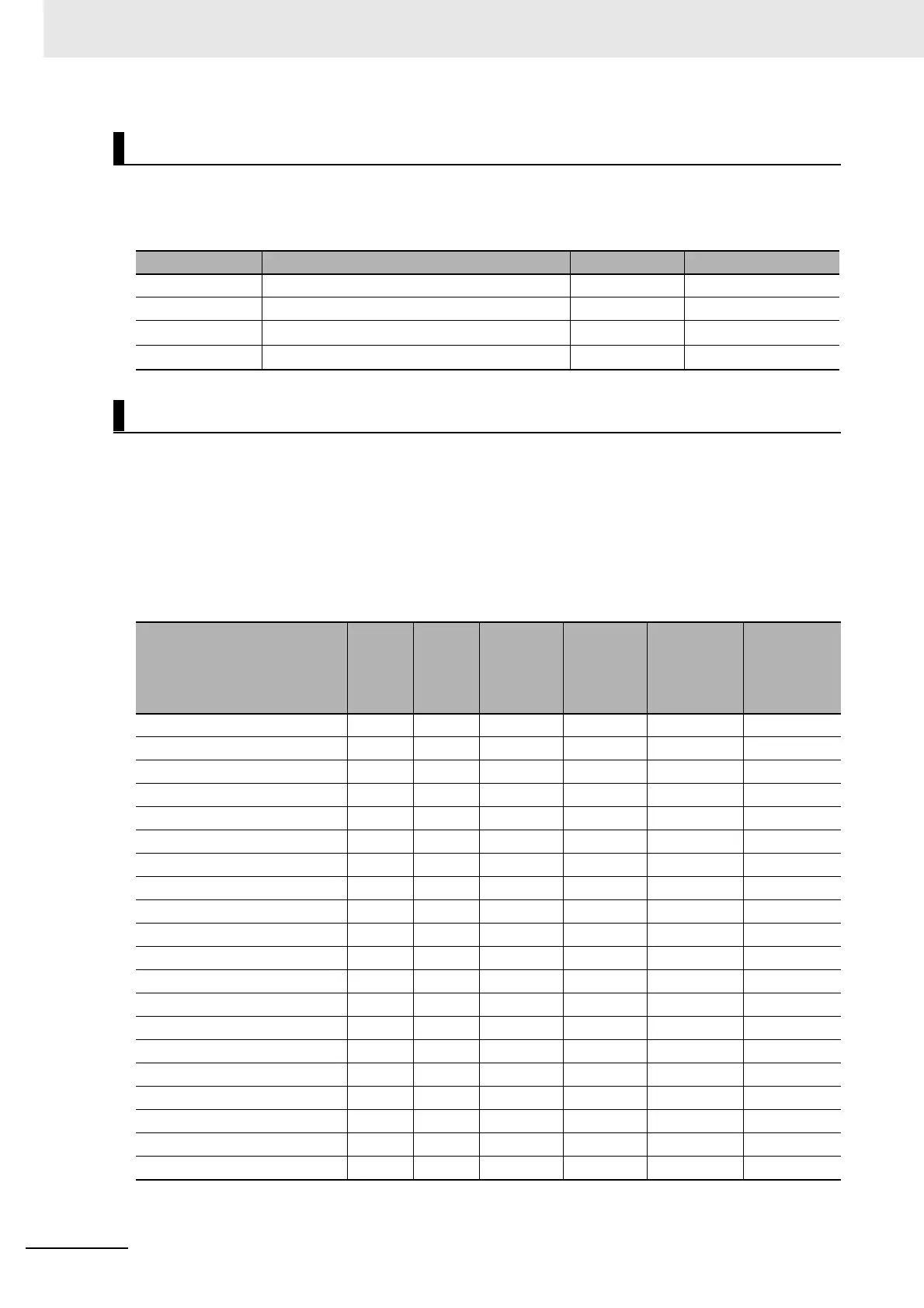
There are four basic servo adjustment parameters as shown in the table below.
If the intended operation characteristics are obtained by adjusting the following 4 parameters, the
adjustments of other parameters are not necessary.
The servo control loop consists of, from the outside, the position loop, the speed loop, and the current
loop in this order.
An inner loop is influenced by outer loops and an outer loop is influenced by inner loops, respectively.
Determine the initial value for each parameter based on the machine configuration and rigidity, inertia
ratio, and other aspects.
Use the following table as a guide to determine the parameter settings for each application.
Parameter Settings for Each Application
• The above values assume that Inertia Ratio 1 (Pn004) is fixed to 300%.
Servo Manual Tuning Method
Parameter No. Name Default value 2nd parameter No.
Pn100 Position Loop Gain 48.0 [1/s] Pn105
Pn101 Speed Loop Gain 27.0 Hz Pn106
Pn102 Speed Loop Integral Time Constant 21.0 ms Pn107
Pn104 Torque Command Filter Time Constant 0.84 ms Pn109
Adjustment of Each Parameter
Application name Inertia Rigidity
Position
Loop Gain
[1/s]
Speed
Loop Gain
[Hz]
Speed Loop
Integral
Time
Constant
Torque
Command
Filter Time
Constant
[× 0.01 ms]
Ball Screw Horizontal Large Low 20 140 35 160
Ball Screw Horizontal Medium Medium 40 80 20 100
Ball Screw Horizontal Small High 80 60 15 80
Ball Screw Vertical Large Low 20 160 45 160
Ball Screw Vertical Medium Medium 40 80 30 120
Ball Screw Vertical Small High 60 60 20 100
Ball Screw Nut Rotation Horizontal
Large Low 20 140 40 160
Ball Screw Nut Rotation Horizontal
Medium Medium 40 100 30 120
Ball Screw Nut Rotation Vertical Large Low 20 160 45 160
Ball Screw Nut Rotation Vertical Medium Medium 40 120 25 120
Timing Belt Large Low 20 160 60 160
Timing Belt Medium Medium 30 120 40 120
Rack and Pinion Large Low 20 160 60 160
Rack and Pinion Large Medium 30 120 40 120
Rack and Pinion Medium Medium 40 100 20 100
Index Table Large Medium 40 120 25 120
Index Table Small High 80 120 20 100
Robot Arm Cylindrical Large Low 15 160 60 160
Robot Arm Cylindrical Medium Medium 25 120 40 120
Other General Uses Medium Medium 30 100 30 150

 Loading...


