10 Troubleshooting and Maintenance
10 - 8
OMNUC G5-series (Pulse-train Input Type) AC Servomotors and Servo Drives User’s Manual
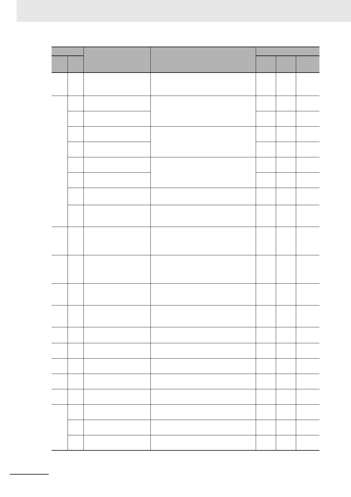
29 0 Error Counter Overflow Error counter value based on the encoder
pulse reference exceeded 2
29
(536,870,912).
√√ –
33 0 Interface Input Duplicate
Allocation Error 1
A duplicate setting for the interface input
signals was detected.
√ ––
1 Interface Input Duplicate
Allocation Error 2
√ ––
2 Interface Input Function
Number Error 1
An undefined number was detected in the
interface input signal allocations.
√ –-–
3 Interface Input Function
Number Error 2
√ ––
4 Interface Output Function
Number Error 1
An undefined number was detected in the
interface output signal allocations.
√ ––
5 Interface Output Function
Number Error 2
√ ––
6 Counter Reset
Allocation Error
The counter reset function was allocated to
something other than input signal SI7.
√ ––
7 Command Pulse
Prohibition Input
Allocation Error
The command pulse prohibition input
function was allocated to something other
than input signal SI10.
√ ––
34 0 Overrun Limit Error The motor exceeded the allowable
operating range set in the Overrun Limit
Setting (Pn514) with respect to the position
command input.
√√ –
36 0-2 Parameter Error Data in the Parameter Save area was
corrupted when the power supply was
turned ON and data was read from the
EEPROM.
–– –
37 0-2 Parameter destruction The checksum for the data read from the
EEPROM when the power supply was
turned ON does not match.
–– –
38 0 Drive Prohibition Input
Error
The forward drive prohibition and reverse
drive prohibition inputs are both turned
OFF.
– √ –
43 0 Encoder Initialization Error An encoder initialization error was
detected.
√ ––
44 0 Encoder 1-rotation
Counter Error
A 1-turn counter error was detected. √ ––
45 0 Multi-rotation Counter
Error
A multi-rotation counter error or phase-AB
signal error was detected.
√ ––
48 0 Encoder Phase-Z Error A serial incremental encoder phase Z
pulse irregularity was detected.
√ ––
49 0 Encoder CS Signal Error A logic error was detected in the CS signal
for serial incremental encoder.
√ ––
55 0 Phase-A Connection Error An error was detected in the external
encoder phase A connection.
√ ––
1 Phase-B Connection Error An error was detected in the external
encoder phase B connection.
√ ––
2 Phase-Z Connection Error An error was detected in the external
encoder phase Z connection.
√ ––
Alarm No.
Error detection function Description and error cause
Attribute
Main
Sub
History
Can be
cleared
Immediate
stop
*1

 Loading...


