104 LD-250 Platform User's Guide 20472-000 Rev B
6.2 Payload Bay Connections - LD-250 Core
Commissioning to verify that the E-Stop functions properly before returning an
AMR to service.
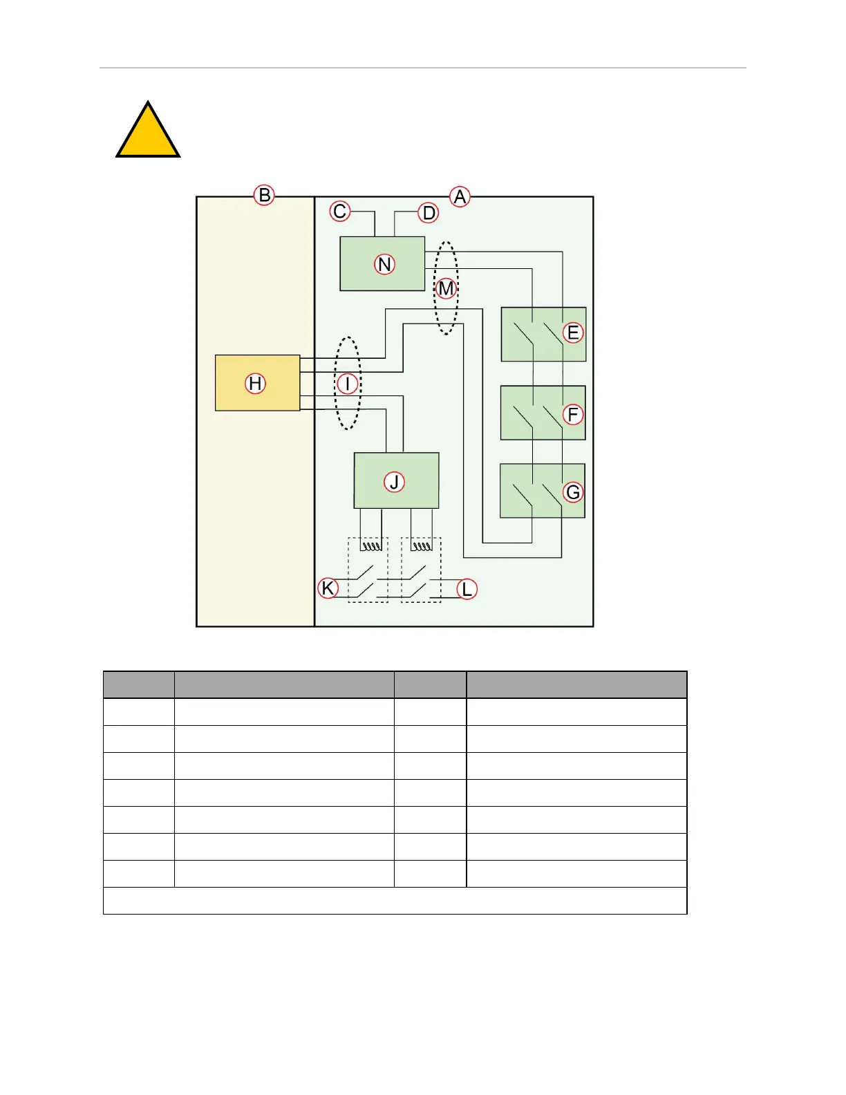
Figure 6-6 E-Stop Chain Diagram
Callout Description Callout Description
A Standard Circuits H User E-STOP
a
B User-Supplied Circuits I User Interface Connector
C E-STOP Source J E-STOP Relay Control Logic
D Ground K Voltage of the Battery
E Operator Panel E-STOP L High Power to Amplifiers
F Right E-STOP (LD-250 only) M HMI Connector
G Left E-STOP (LD-250 only) N Factory E-STOP
a
Close with a jumper if unused. Both channels must open independently when used.