Chapter 6: Connectivity
User Bumper
The LD-250 Core's User Bumper Mini-Fit
®
2 x 4 connector provides 6 circuits for optional
user-supplied payload bumpers.
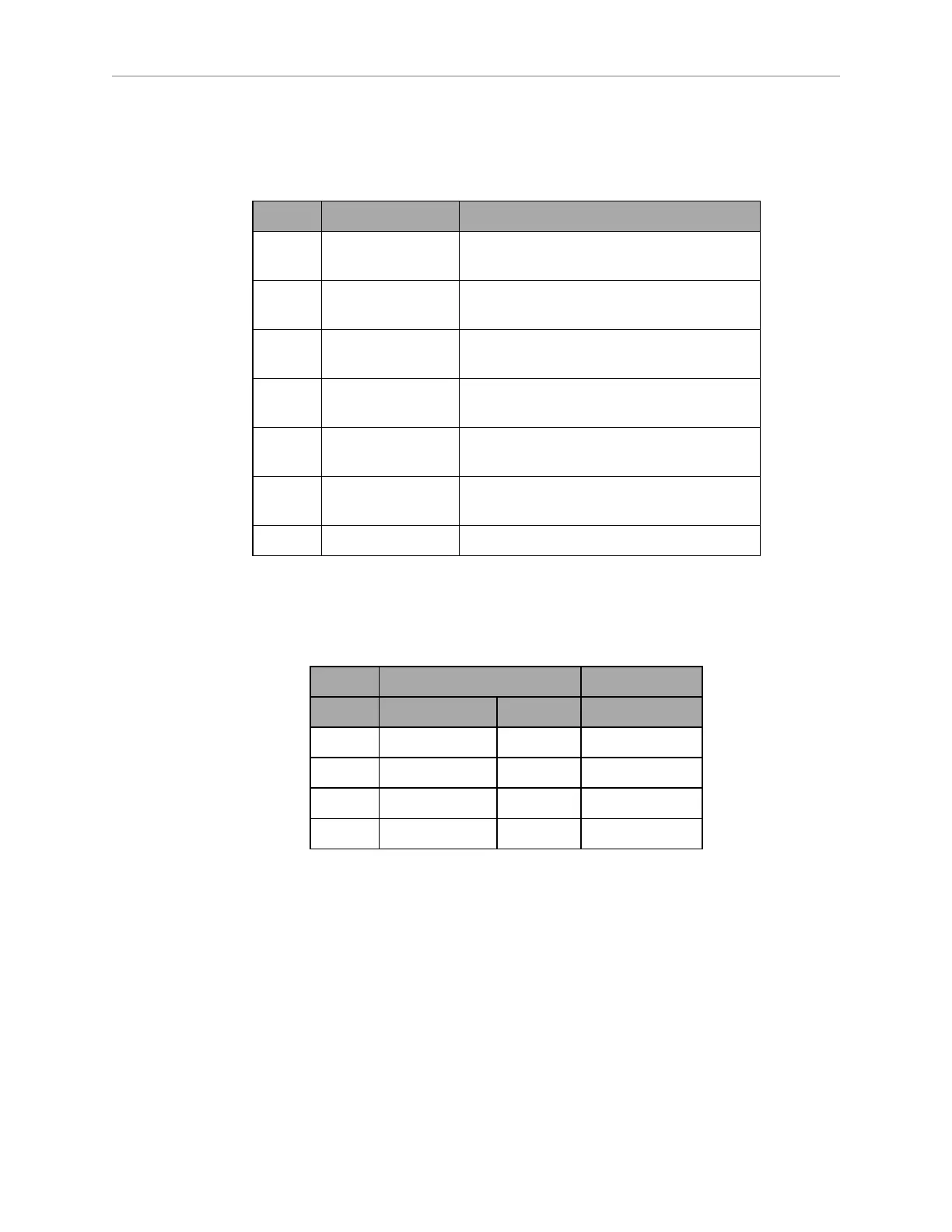
Pin No. Designation Notes
1 USER_BUMPER_1 Short to E-STOP_SRC to signal bumper hit
Front left bumper sensor.
2 USER_BUMPER_2 Short to E-STOP_SRC to signal bumper hit
Front center bumper sensor.
3 USER_BUMPER_3 Short to E-STOP_SRC to signal bumper hit
Front right bumper sensor.
4 USER_BUMPER_4 Short to E-STOP_SRC to signal bumper hit
Rear right bumper sensor.
5 USER_BUMPER_5 Short to E-STOP_SRC to signal bumper hit
Rear center bumper sensor.
6 USER_BUMPER_6 Short to E-STOP_SRC to signal bumper hit
Rear left bumper sensor.
7, 8 E-STOP_SRC 12 V E-STOP Source Output @ 10 mA
Aux Power
The LD-250 Core's Aux Power Mini-Fit
®
3 x 2. connector provides auxiliary power outputs.
Refer also to Power Consumption on page 79 which specifies limits on power draw.
Designation
Pin No. Hardware Software Notes
1, 2, 3 GND
4 AUX_5V_OUT Aux_5V 5 V @ 1 A max
5 AUX_12V_OUT Aux_12V 12 V @ 1 A max
6 AUX_20V_OUT Aux_20V 20 V @ 1 A max
User Power
The LD-250 Core's User Power Mini-Fit
®
2 x 6 connector provides battery power for payload
devices.
Refer also to Power Consumption on page 79 which specifies limits on power draw.
IMPORTANT: Pressing an E-Stop interrupts the power output on pins 11 and
12 (SAFE_VBAT_OUT). This is useful if you want to interrupt power to both the
AMR and its payload devices.
20472-000 Rev B LD-250 Platform User's Guide 105