106 LD-250 Platform User's Guide 20472-000 Rev B
6.2 Payload Bay Connections - LD-250 Core
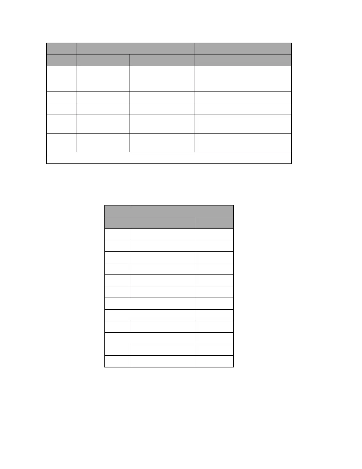
Designation
Pin No. Hardware Software Notes
1, 2,
3, 4,
5, 6
GND
7 SW_VBAT_OUT1 Battery_Out_1 VBAT @ 4 A max (switched in SW)
8 SW_VBAT_OUT2 Battery_Out_2 VBAT @ 4 A max (switched in SW)
9, 10* SW_VBAT_OUT34 Battery_Out_3_and_4 VBAT @ 10 A max (switched in SW)
Limit to < 5 A per pin.
11, 12* SAFE_VBAT_OUT SW_VBAT_OUT34 gated by
dual-channel E-STOP relays
*9, 10, 11, and 12 share the 10 A of current.
HMI Panel (Operator Panel)
The LD-250 Core's HMI panel HDB15F connector provides circuits for the Operator Panel
screen and its buttons (ON, OFF, EMERGENCY OFF, and Brake Release.).
Designation
Pin No. Hardware Software
1 RS422_HMI_TX+
2 RS422_HMI_TX-
3 MOTOR_BRAKE
4, 5 E-STOP_FP_1H, _2H
6 RS422_HMI_RX+
7 RS422_HMI_RX-
8 START_BUTTON
9, 10 E-STOP_FP_1L, _2L
11 HMI_5V_SW HMI_Power
12, 14 GND
13 OFF_BUTTON
15 FBAT_ALWAYS
If you are using the optional touchscreen instead of the Operator Panel, it is possible to use
this port for custom connections. However, Omron recommends that you use the User Inter-
face port, which is intended for customization. See: User Interface (Brake and E-Stop) on page
103.