16 LD-250 Platform User's Guide 20472-000 Rev B
1.2 Product Description
You can move the operator panel to any preferred position on your payload structure.
However, because the operator panel contains one of the three E-Stop buttons, there are
important safety considerations when relocating or removing this panel. See: Positioning
an Optional Payload E-Stop on page 126 and Operator Panel (HMI)on the Payload on page
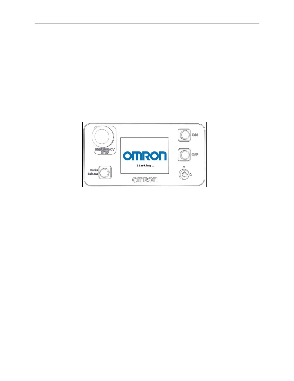
90 for more information. The standard Operator Panel includes:
o
6-line status and message display screen.
o
E-Stop button.
o
Vehicle power ON and OFF buttons.
o
Brake release button.
o
2-position key switch for access control. Lock the key switch to disable the off but-
ton and prevent accidental or unauthorized shutdowns.
Figure 1-4 Operator Panel
Also available is an optional touch screen that shows more AMR status information
and provides additional functions. See Touchscreen on page 188.
l
Automated docking station
The docking station enables the LD-250 to charge itself, without user intervention. It
includes a wall-mount bracket and a floor plate, for a choice of installation methods. See
Installing the Docking Station on page 58.
When the docking station is not occupied, a manual charging cord enables you to
charge a battery outside the LD-250.
l
A USBflash drive containing software and documentation.
In addition to the items included with every LD-250, you need at least one joystick per robot
fleet. Use this joystick to manually drive the LD-250 and to create a digitized map of the work
environment.
For a fleet of AMRs, the Fleet Operations Workspace Core (FLOW Core) software (running on a
Fleet Manager appliance) shares the map between all AMRs in the fleet. This provides a com-
mon frame of reference for navigation and localization, preventing contention between AMRs.
Figure 1-5 shows the joystick and Ethernet port, located on the right rear skin.