2-16
Symbol Name Specification
Out-
put
MA Multi-function contact
output (Normally open:
During operation)
Relay output
1 A max. at 30 V DC
1 A max. at 250 V AC
MB Multi-function contact
output (Normally
closed:
During operation)
MC Multi-function contact
output common
P1 Multi-function photo-
coupler output 1
(Fault)
Open collector output 50 mA max.
at 48 V DC
P2 Multi-function photo-
coupler output 2
(Fault)
PC Multi-function photo-
coupler output com-
mon
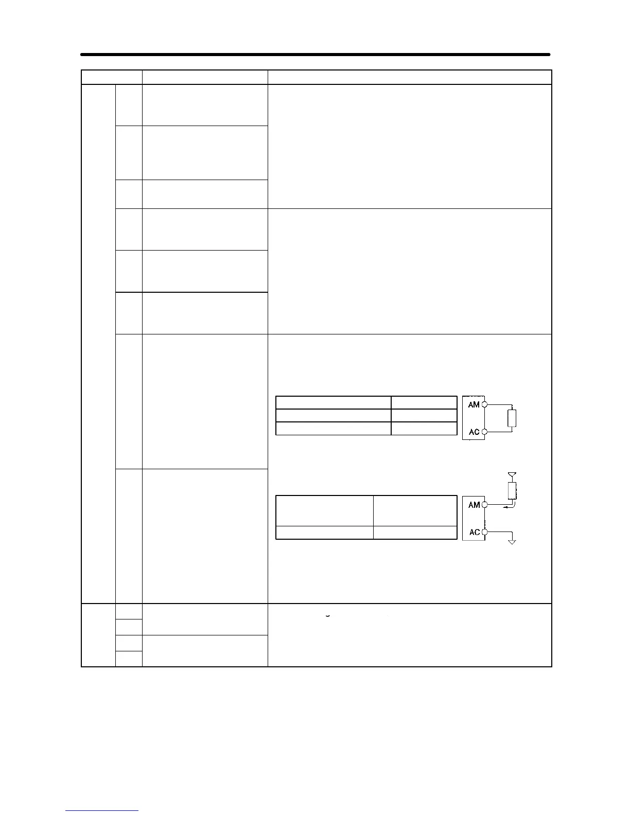
AM Multi-function analog
output
· Analog output: 2 mA max. at 0 to 10 V DC
· Pulse train output (max. output voltage: 12 V DC)
(See note 4.)
When Used as Voltage Output
Load impedance
1.5 kW min.
10 kW min.
Output voltage (insulation type)
+5 V
+10 V
Load
imped-
ance
External
AC Multi-function analog
output common
When External Power Supply is Used
Note Donot usea 5-VDC or 24-VDC external power
supply.Doing socan causeinternal circuitdam-
age or malfunctioning.
Input current (mA)
from external power
supply
16 mA max.
External power supply (V)
12 V DC (±5%)
power
supply
12 V DC
Load
imped-
ance
Input cur-
rent
16 mA
max.
External power
supply ground
Com-
R+
Receiver side Conforming to RS-422/485