Outline of Serial Communications Section 5-1
120
5-1 Outline of Serial Communications
This section explains how to perform serial communications.
Introduction
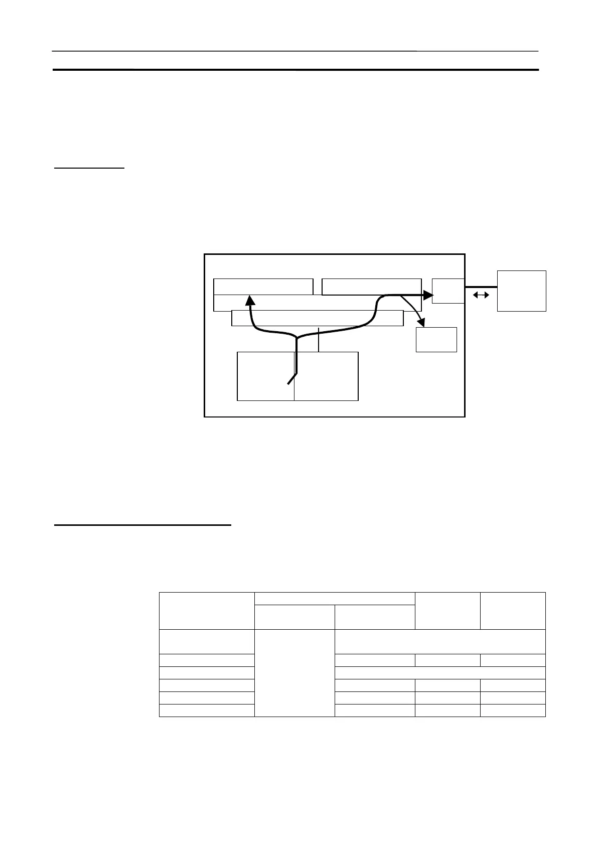
The CX-Simulator can debugs serial communications using (1) actual com-
munications to an external serial communications device using a COM port on
the computer,(2) screen display of send messages, or (3) input/output from/to
a file.
Note
1. Serial communications cannot be performed when the CX-Simulator is
started and the online connection is made from the CX-Programmer.
2. Refer to 6-3 Serial Communications of CS/CJ Series Programming Manual
for the outline of CS/CJ-series serial communications.
Supported Protocols and Units
The CX-Simulator supports Host Link (SYSMAC WAY), NT Link, and
No-protocol as a protocol for serial communications. These protocols support
differently depending on a Unit that performs serial communications. The
relationship between serial communications protocols and Units is shown
below.
CPU Unit
Hardware
Protocol
Peripheral port
(Port 1)
RS-232C port
(Port 2)
Serial
Communica-
tions Board
Serial
Communica-
tions Unit
Host Link
(SYSMAC WAY)
Yes (FINS/C-mode communications)
Protocol macro - No No
NT LInk (1:N mode) Yes (Only Unit No.0 connectable)
No-protocol Yes - -
Peripheral bus No - -
Loopback test
No
- No No
Yes: Supported No: Not supported -: Does not exist
Computer
Debugger: Screen displa
FinsGateway
Simulator
Communi-
cations Unit
CPU
Unit
External
serial com-
munications
device
RS-232C
(1)
(3)
COM
ort
Files
(2)
Virtual Communications Unit
Serial Communications Server
 Loading...


